User's Manual
43
Table 4-1 Alarm port description
Icon Description
1, 2, 3, 4, 5, 6, 7, 8, 9, 10, 11, 12, 13,
14, 15, 16
ALARM 1 to ALARM 16. The alarm becomes active in low
voltage.
NO1 C1, NO2 C2, NO3 C3
There are four groups of normally open activation output
(on/off button).
Ground cable.
485 A/B
485 communication port. They are used to control devices
such as decoder. 120 Ω should be parallel connected
between A, B lines if there are too many PTZ decoders.
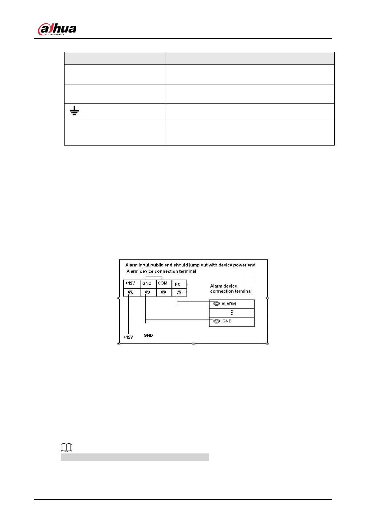
4.3.2 Alarm Input
Refer to the following figure for more information.
●
Grounding alarm inputs which includes NO (Normally Open) and NC (Normally Closed) type.
●
Parallel connect COM end and GND end of the alarm detector (Provide external power to the
alarm detector).
●
Parallel connect the Ground of the DVR and the ground of the alarm detector.
●
Connect the NC port of the alarm sensor to the DVR alarm input (ALARM).
●
Use the same ground with that of DVR if you use external power to the alarm device.
Figure 4-3 Alarm input
4.3.3 Alarm Output
●
Provide external power to external alarm device.
●
To avoid overloading, read the following relay parameters table carefully.
●
RS-485 A/B cable is for the A/B cable of the PTZ decoder.
4.3.4 Alarm Output Relay Parameters
Refer to the actual product for relay model information.
 Loading...