D-11
(5) Leading Edge Tilt Adjustment
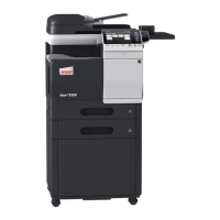
1. Print the test pattern.
2. Draw lines 100 mm (A and B) from the center of
the test pattern, as shown in the illustration.
1382D007AA
A
B
100 mm
100 mm
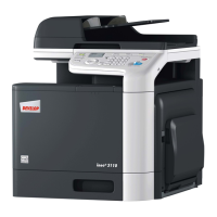
3. Load the test pattern into the Automatic Docu-
ment Feeder, and then print five single-sided cop-
ies.
NOTE
• The test pattern should be positioned vertically.
1382U027AA
4. Measure the lengths a and b on the copies of the
test pattern and, if there is a large shift, adjust it
according to the following procedure.
Standard values of a and b = ± 1.0 mm
1382D008AA
a
b
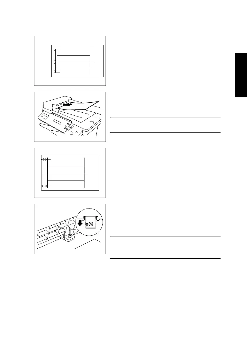
<If A is longer than B>
Using a coin, loosen the shoulder screw shown in the
illustration, and then slide the scale on the Automatic
Document Feeder toward you.
NOTE
• After finishing the adjustment, be sure to tighten
the loosened shoulder screw.
1382U028AB