M-25
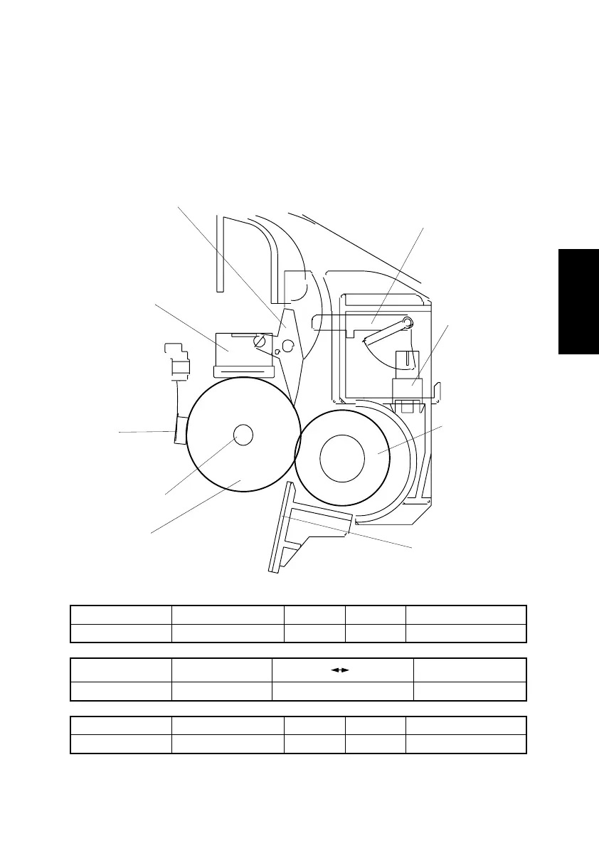
12. FUSING UNIT
12-1. Overview
• The toner image transferred onto the paper is securely fixed to the paper.
• A heated roller system is used as the fusing system. The paper, to which the toner
image has been transferred, is fed between the Fusing Roller heated by the Fusing
Roller Heater Lamp and the Pressure Roller. This permanently fixes the toner image in
the paper.
Electrical Parts Control Signal Blocked Unblocked WIRING DIAGRAM
PS1 PWB-P MPJ8P-3 L H F~G-2
Electrical Parts Control Signal
Low temp. High temp.
WIRING DIAGRAM
TH1 PWB-P MPJ2P-1 Analog Input F-2 to 3
Electrical Parts Control Signal ON OFF WIRING DIAGRAM
H1 PU-1 CN1PU-1-3 L H I-7
Pressure Roller
Fusing Roller
Fusing Roller
Heater Lamp (H1)
Fusing Entrance
Guide Plate
Thermostat (TS1)
Fusing Paper Separator Finger
4136M520AA
Exit Sensor
(PS1)
Thermistor
(TH1)
Actuator