E-9
<Installation Procedures>
NOTE
• When replacing a part comprising the Fusing Unit individually to correct an image prob-
lem or a defective part, see D-26 (“Disassembly of the Fusing Unit” of DIS/REASSEM-
BLY, ADJUSTMENT).
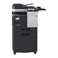
7. Remove two screws, unplug three connectors,
and remove the Fusing Unit.
NOTE
• The surfaces around the Fusing Unit are very hot.
Use utmost care not to touch any surfaces other
than the Fusing Unit.
4980E002AB
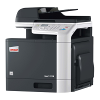
8. Remove the Fusing Unit.
4980E003AA
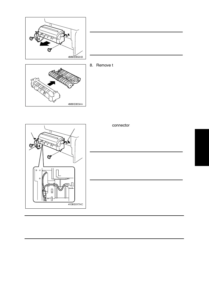
1. Connect connector A.
2. Mount the Fusing Unit in the printer and secure it
in position by tightening the two screws.
3. Connect connectors B and C.
NOTE
• When installing the Fusing Unit, route the harness
as shown in the illustration and make sure that no
part of the harness is wedged between the Fusing
Unit and printer.
4136E017AC
A
B
C