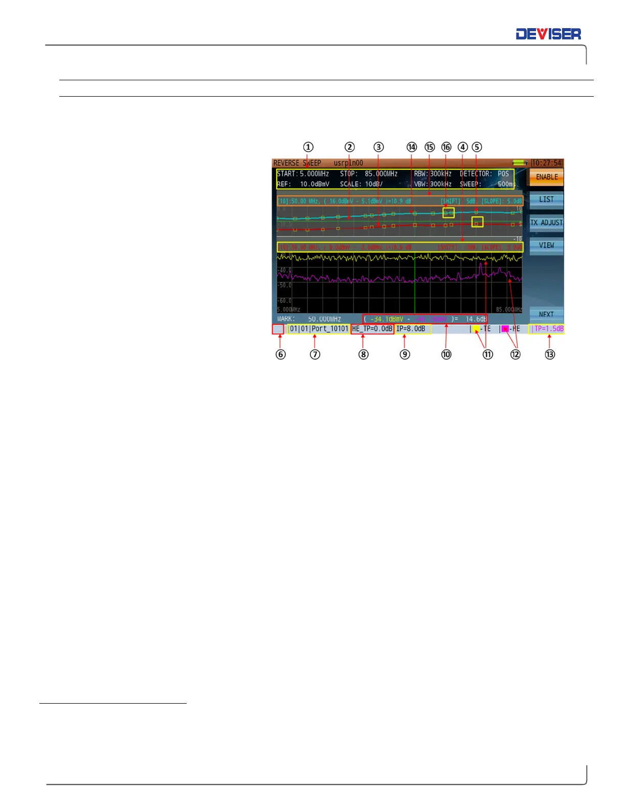
12-3.3 Reverse Path Sweep Display Overview
To explore the Reverse Path Sweep display interface, refer to the numbered figure and associated
definitions below.
1.
Spectrum analyzer settings. Copied
from upstream spectrum mode.
2.
Green line depicts signal levels trans-
mitted to / received from HE DS1610.
3.
Assembled sweep frequency response
trace.
*
4.
Reverse sweep transmission
parameters. In this example:
[10]:50MHz, (frequency of the active
marker is the 10
th
inserted sweep point
of the reverse sweep trace, at 50MHz),
8dBmV (DS2831 US transmit level) - -
2.6dBmV (received DS level from the
DS1610)=10.6dB loss in the US path
being measured.
[SHIFT]: -3dB
[SLOPE]: 5.0dB
[SHIFT]: Adjusts the transmitted signal level for all frequency points.
[SLOPE]: Transmitted level difference between 1
st
and last inserted sweep points. -10~ +10dB.
5.
The DS2831 upstream sweep transmit frequencies (sweep points) received by DS1610 at the headend.
6.
FSK sync icon. If the DS2831 and DS1610 are not synced, it will remain red and display “Offline”. When
registration starts, it will show “Send Pilot…” & “Waiting Pilot…”. When registration is successful and
remains active, the icon will alternate between yellow and green.
7.
DS1610 upstream ID#. For example, for the 01/01/Port_10101 shown above, the first 01 is the board # of
the DS1610, the second 01 is the port # of the DS1610 - 01 board, and Port_10101 is the port name.
8.
Headend test point compensation
9.
Insertion point compensation:
10.
The difference in amplitude level between the local spectrum trace and the received headend/Hub
spectrum trace at the marker position.
11.
Field spectrum trace: at the DS2831 field location.
12.
The spectrum trace sent to the DS2831 as it is received by the DS1610 at the headend, from the DS2831
13.
Local test point compensation value.
*
The example here shows a trace formed from 16 connected discrete-frequency RF signals initially transmitted upstream by the DS2831, then
received by the DS1610 at HE. The DS1610 then re-transmits those sweep points through the FSK DS carrier frequency, back to the DS2831. Up to 16
discrete-frequency RF signals can be transmitted upstream by the DS2831. The sweep technician will determine how many sweep points can be
used based on the local network health, spectrum space available, and amount of bandwidth already occupied by live signals.