Part II: Settings and Measurements
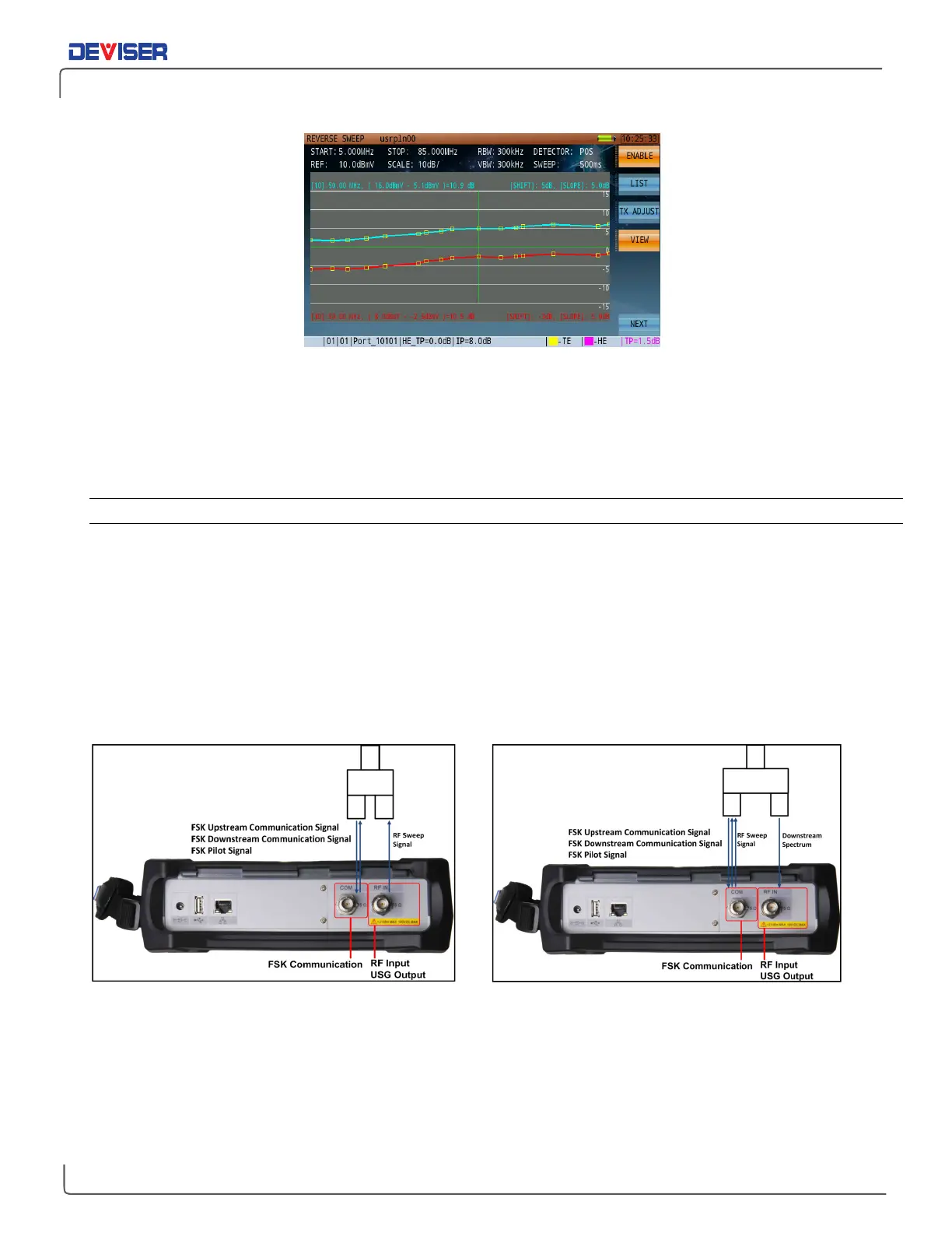
Reverse Path Sweep Full Screen Display
14.
Reference return sweep trace.
15.
Reference return sweep trace transmit and receive parameters.
16.
The reference return sweep trace upstream sweep transmit frequencies (sweep points) received by
DS1610 at the headend.
12-3.4 Reverse Path Sweep Operation
From the
Home
menu, press
Upstream
(F2) and use the rotary knob to open the reverse path sweep mode.
First, press
Setup
(F4). Set up the following parameters as desired for your measurement: pilot frequency,
uplink frequency, downlink frequency, pilot level, insertion point compensation, reverse path sweep slope
and reverse sweep port.
Reverse sweep port can be toggled between the RF port and COM port. The FSK communication port must
use COM port. If the user sets up the RF port as a reverse sweep port, the port signals should be configured
as shown (below, left). In this configuration, the RF port cannot view the local spectrum image at the same
time as reverse path sweep.
RF Port as Reverse Path Sweep Port COM Port as Reverse Path Sweep Port
If the user sets up the COM port as a reverse sweep port, the port signals should be configured as shown
(above, right). Now RF port can receive local spectrum.
Once the parameters listed above have been set, press
Login
(F1). Synchronization messages will appear in
the lower left corner of the display: “Send pilot …”, “Waiting Pilot…” (with a red icon). When the icon begins
alternating between yellow and green, the DS2831 and DS1610 are connected and the DS2831 will start
displaying the sweep frequency response trace.