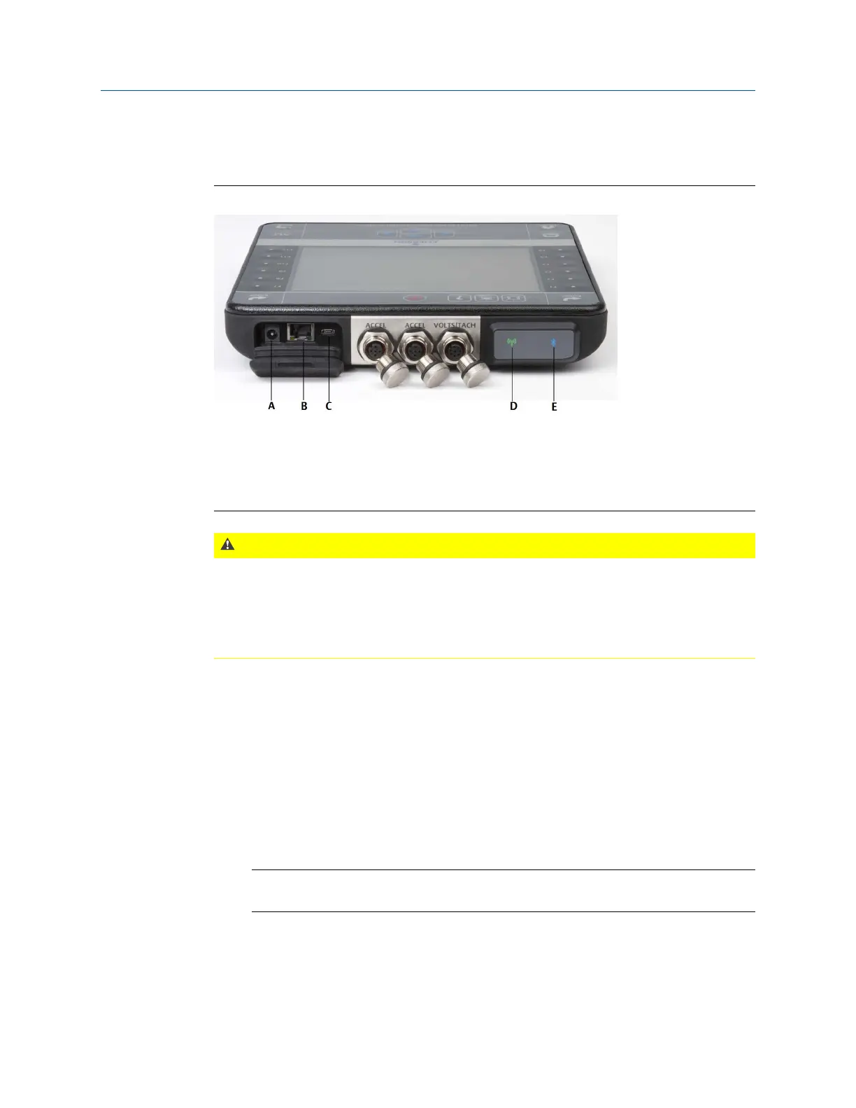
2.3 Top view
ConnectorsFigure 2-2:
A. Power supply connector.
B.
Ethernet port.
C. Micro USB port.
D. Wireless LED.
E. Bluetooth
®
LED.
CAUTION!
To prevent damage to the analyzer:
• Do not connect a signal outside the range of 0 to 24 volts into the Accel input of the CSI
2140.
• Do not connect a signal outside the range of +/- 24 volts into the Volts / Tach input of the
CSI 2140.
2.4 Turn on the analyzer for the first time
You need to activate the battery pack before you can turn on the analyzer for the first time.
The battery pack is shipped in storage mode to protect the battery charge. Connect the
provided power supply cord into an outlet and to the analyzer to activate the battery pack.
Procedure
1.
Connect the provided power supply cord into an outlet and to the analyzer.
Note
Refer to precautions for the battery pack and power adapter.
The Battery LED is amber to indicate the battery pack is charging. The analyzer is
activated.
Introduction to the analyzer
8 MHM-97432 Rev 7