10.5.4 Set up the measurement points on measurement planes
1. From the Balance main menu, press F3 Job Setup.
2.
Press Enter or F4 Meas Plane Setup.
The Measurement Plane Setup screen appears.
3. Ensure the correct measurement plane is displayed at the top of the screen.
Press Enter to go to the next plane, if necessary.
4. Use the up and down arrow keys to select a measurement point.
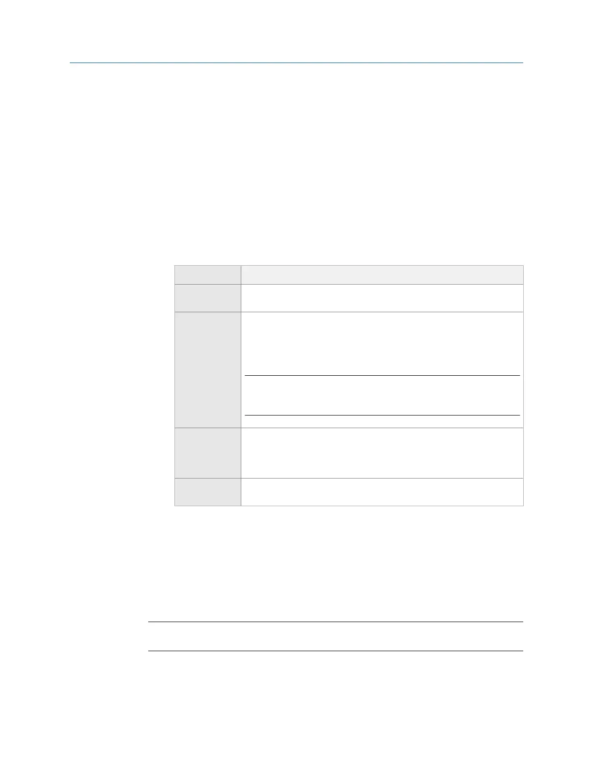
5. For each measurement point, change the following options as necessary.
Option Description
F9 Edit MPT ID Enter up to three characters to identify the measurement point for data
acquisition, reports, and future setups.
F10 Enter MPT
Angle
Enter a value between 0 and 359 degrees relative to top-dead-center
(TDC). The analyzer uses the measurement point location for future
setups, on graphs, and in some calculations in the Calculator Mode, such as
Estimate Trial Weight.
Note
The analyzer does not use the measurement point location to calculate
balance correction.
F11 Enter MPT
Channel
Enter the channel between A and D for the measurement point. If you set
the mux option to EXT, enter a number between 1 and 8. The analyzer
does not display this option if you disabled the mux option. See
Section 10.4.5.
F12 MPT Rad/Ax Select Radial or Axial for the sensor location. Each measurement plane can
have one axial measurement point.
10.6 Weight Plane Setup
A weight plane is where you add or remove weights on the equipment. Each weight plane
must have at least one measurement plane. The Weight Plane Setup screen is the last step
in Job Setup for Advanced Balance mode. Set up one weight plane at a time.
Note
This is available only in Advanced Balance mode.
Balance
MHM-97432 Rev 7 319