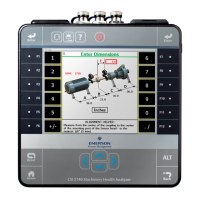
6.6 Tachometers
6.6.1 Set up a tachometer in Analyze
Note
By default, the analyzer is set up to use the CSI 404 tachometers. The analyzer supports
tachometer/RPM measurements up to 100,000 RPM.
Procedure
1.
From the Analyze main menu, press F1 Manual Analyze > F7 Tach Setup.
The Tachometer Setup screen appears.
2. Set the following options as necessary.
Option Description
F2 Pseudo Tach Enable Pseudo Tach for time synchronous averaging or order tracking
intermediate shafts in gearboxes that cannot be accessed directly. Use the
Pseudo Tach to produce the turning speed signal. The analyzer uses the
following formula: (Incoming tachometer frequency) X ((tach frequency X
the number of teeth on the tached shaft)/number of teeth on the pseudo
shaft). Disable Pseudo Tach when you can use the tachometer directly on a
shaft. The default is Disabled.
F3 Tached Shaft (Only available when Pseudo Tach is enabled.) If the reflective tape is on the
input shaft, enter the number of teeth on the tached shaft, which is the
shaft with the tachometer. The default is 1.
F4 Pseudo Shaft (Only available when Pseudo Tach is enabled.) Enter the number of teeth on
the internal shaft. The analyzer calculates the pseudo tach frequency based
on the number of teeth specified for the tached shaft and pseudo shaft.
The default is 1.
F5 Tach Power Set the analyzer to power the tachometer. If you enable this option, you
can leave the switch on for the CSI 430 SpeedVue Sensor during the Laser
Speed Detection Analysis Expert. The default is On.
F7 Set Trigger
Edge
Set the trigger to occur on the rising edge or falling edge of a waveform.
The default is Rising Edge.
F8 Set Trigger
Level
Enter the value between -100 and 100 required to start a tachometer
pulse. For Level measurement, set the input that is the source of the
trigger. The default is 2.0 Volts.
F9 Set Edge
Delay
Enter the number of seconds between 0 and 16 that occurs between each
tachometer pulse. This helps prevent double triggering. The default is 0.0
seconds.
F10 Show RPM
F10 Hide RPM
View or hide the last RPM the tachometer read and the time between each
reading. A last time value of 0 indicates the tachometer is continuously
reading the RPM.
Analyze and Advanced Analyze
116 MHM-97432 Rev 7

 Loading...


