Patch 115
Note: You can open or merge patch data from other show files, see Partial Patch Opening
(on page102) and Partial Patch Merging (on page105) for more information.
A 1-to-1 patch can be created from the Clear display. See Clearing thePatch (on page142)
Patch Main Displays
To begin patching your show, you must first open the patch display. To open the patch display, press
[Address/Patch] twice or press [Displays] and then {Patch}. [Tab] [1][2] can also be used to open
Patch.
The patch display will open in the selected tab, and the CIA will display patch controls.
From within the patch display, you can open the Device List to use RDM to patch any RDM com-
patible devices. For more information about Device List, see Using Device List (on page136).
For patching fixtures, there are two different patch modes: patch by channeland patch by address.
Eos defaults to patch by channel mode. Pressing [Format] while in the Patch display will toggle the
mode between patch by channel and patch by address.
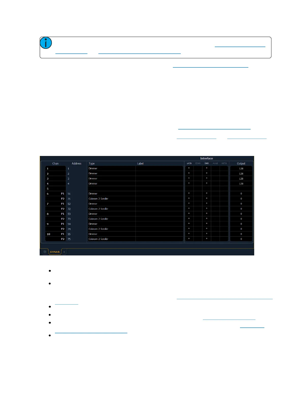
The patch screen will display the following information if available:
Channel - the patched channel number. In patch by address mode, channel will appear blank
if not currently patched.
Address - the patched output address. In patch by channel mode, address will appear blank if
not currently patched. Pressing [Data] toggles the display from showing address as patched
by the user, output address, and the port/offset. See Using Output Address vs Port/Offset (on
page117).
Type - device or dimmer type that is patched.
Label - displays the assigned label of the channel or address. See Labeling (on page125).
Interface - displays which interfaces will be used for the device. See {Interface} in {Patch} Dis-
playand Settings (on page132).
Output - displays the current live intensity level. Value is displayed as 0 through 255, with 255
being full.