132 Eos Family Operations Manual
The shutter frame assembly parameter allows for the shutter assembly to be turned. When {Invert
Rack} is disabled, a encoder will move the frame assembly from the right. When enabled, the frame
assembly will move from the left.
Settings in Patch
Softkeys available for use while in patch include {Patch}, {Attributes}, and {Database}. Pressing any of
these softkeys opens a paged view of the patch display and redraws the CIA to an expanded view of
fields related to the selected page.
When creating and editing your patch, page through each of these softkeys individually to enter
more specific data about your selected device.
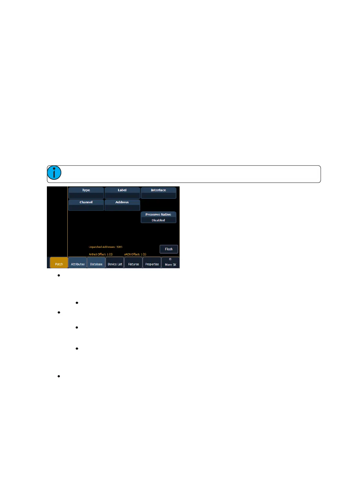
{Patch} Display and Settings
With patch open, Eos defaults to this display. It provides access to data input fields that you may use
to define devices in your lighting system.
Note: The Artnet and sACN offset will display here.
{Channel} - In the patch display, all channels are displayed in numerical order. When multiple
devices are patched to the same channel, the channel number is only displayed in the first
row, additional devices are indicated with part extensions (example P2) on the next row of the
table.
Select the channel number using the control keypad or the direct selects.
{Type} - Eos defaults to patching dimmers. To specify a specific device type for the selected
channel, press the {Type} button from the CIA.
The two columns on the left side of the CIA are pageable and show manufacturer
names. The four columns to the right of the manufacturer’s list are pageable devices
that are available from the selected manufacturer for patching.
Selecting a specific manufacturer repaints the display with all devices that are available
from that manufacturer. After you select a device, the fixture/ device type appears in
the command line, in the {Type} box in the CIA, and in the “Type” field for that channel
in the patch display.
{Label} - An optional user-defined label. You can use the [Label] key to display the virtual PC
keyboard on the CIA. Pressing {Label} or [Label], after a label has already been assigned, will dis-
play the label on the command line for editing purposes. Pressing [Label] [Label] will clear the
text.