Programming manual.
CNC 8070
10.
ELECTRONIC THREADING AND RIGID TAPPING.
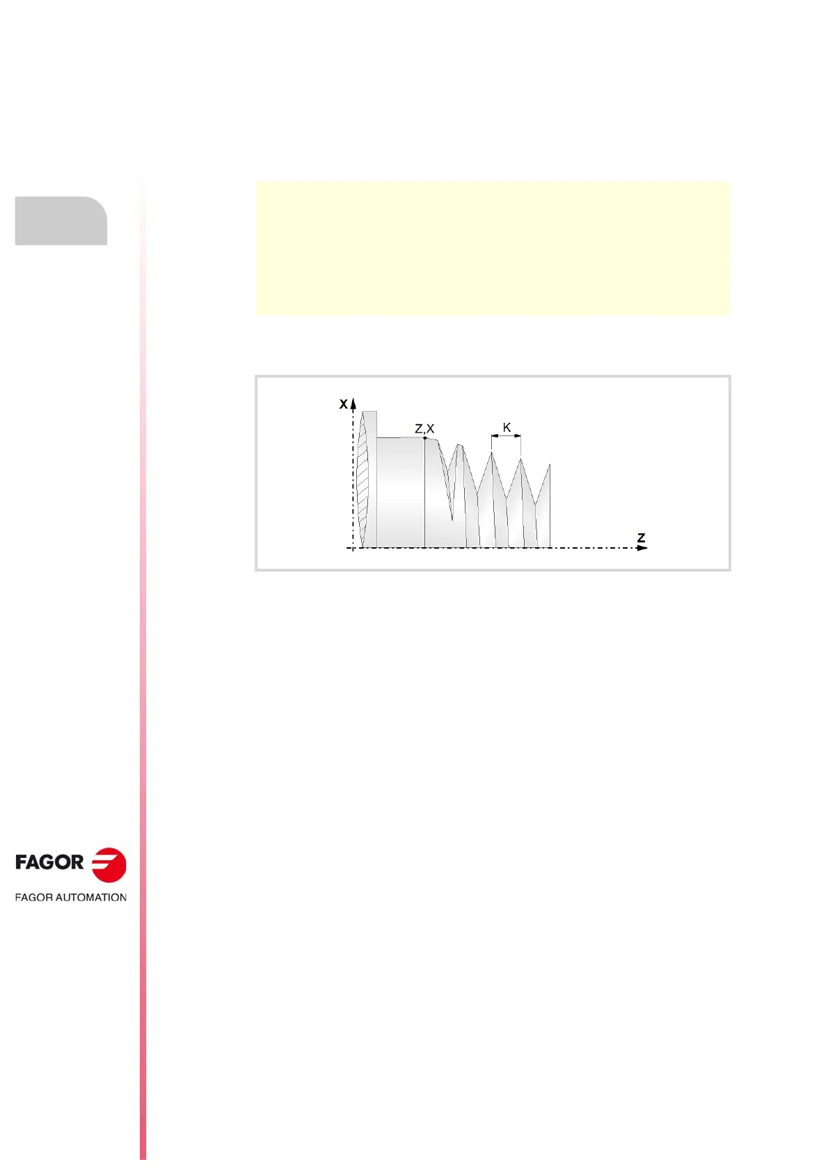
Electronic threading with variable pitch (G34)
·186·
(REF: 1709)
Starting thread pitch.
• The pitch is defined by the letters "I", "J" or "K" depending on the active plane.
• When interpolating several axes in the electronic threading, the pitch is defined on one
of the axes; not on the path.
• If the starting pitch of the thread is not programmed, the CNC acts as follows.
1 If no G33 or G34 has been programmed earlier, the CNC will issue an error message.
2 If a G33 has been programmed earlier, the starting pitch of G34 will be the pitch of the
last G33 programmed.
3 If there is no G33, but a G34 has been programmed earlier, the starting pitch of G34 will
be the final pitch of the last G34 programmed.
Spindle angular position.
Spindle angular position (within ±359.9999º) for the starting point of the thread. With this
parameter, it is possible to make multi-entry threads. Programming it is optional; if not
programmed, the function executes the thread at 0º (same as programming Q1=0).
Increment (K1>0) or decrement (K1<0) of the thread pitch per spindle turn.
The function executes a thread with an I/J/K pitch in the first turn, I/J/K+K1 in the second
one, I/J/K+2*K1 in the third one and so on. Parameter K1 may be positive (pitch increment)
or negative (pitch decrement) with the following limitations.
• If K1 is positive, it cannot be greater than or equal to twice the starting pitch.
• If K1 is positive, when incrementing the pitch while machining, none of the threading axes
can exceed its maximum feedrate (parameter MAXFEED).
• If K1 is negative, the pitch while machining cannot reach zero or be negative, otherwise,
the CNC will issue the corresponding error message.
The pitch increment depending on the starting pitch, final pitch and distance may be
calculated as follows.
K1 = ( (final pitch)² – (starting pitch)² ) / 2 * (distance)
G17 G18 G19 Letters "I", "J" and "K" are associated with the first, second and third
axis of the channel respectively.
G20 Letters "I", "J" and "K" are associated with the abscissa, ordinate and
perpendicular axes of the defined plane.
Example:
Electronic threading on the Z axis and in different planes (configuration of XYZ axes in the
channel).
G17 (XY plane)
G34 Z40 K2 K1=1
G18 (ZX plane)
G34 Z40 K2 K1=1
G19 (YZ plane)
G34 Z40 K2 K1=1
G20 Z1 Y2 X3
G34 Z40 I2 K1=1
G20 Y1 Z2 X3
G34 Z40 J2 K1=1
G20 Y1 Z3 X2
G34 Z40 K2 K1=1