Programming manual.
CNC 8070
KINEMATICS AND COORDINATE TRANSFORMATION
19.
Coordinate systems (#CS / #ACS).
·327·
(REF: 1709)
19.4.1 Define a coordinate system (MODE1).
Both instructions use the same programming format and may be used together or separately.
#CS DEF [{n}] [MODE 1, {V1}, {V2}, {V3}, {1}, {2}, {3}]
#ACS DEF [{n}] [MODE 1, {V1}, {V2}, {V3}, {1}, {2}, {3}]
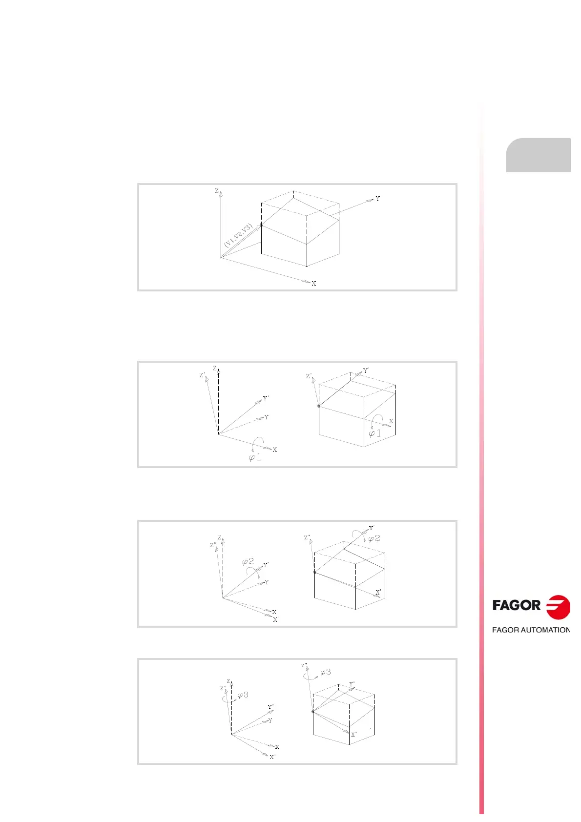
This mode defines an inclined plane as a result from rotating the amounts indicated in 1,
2, 3 first around the first axis, then around the second axis and finally around the third axis
respectively.
V1, V2, V3 Components of the translation vector.
Coordinate origin of the inclined plane with respect to the current part zero.
1, 2, 3 Rotation angles to build the inclined plane.
First, rotate around the (X) axis the amount indicated by 1. In the figure, the new coordinate
system resulting from this transformation is called X Y' Z' because the Y, Z axes have been
rotated.
Then, rotate around the 2nd axis (Y'), the amount indicated by 2. In the figure, the new
coordinate system resulting from this transformation is called X' Y' Z'' because the X, Z axes
have been rotated.
And last, rotate around the third axis (Z''), the amount indicated by 3.