Programming manual.
CNC 8070
1.
CREATING A PROGRAM.
List of "G" functions.
·40·
(REF: 1709)
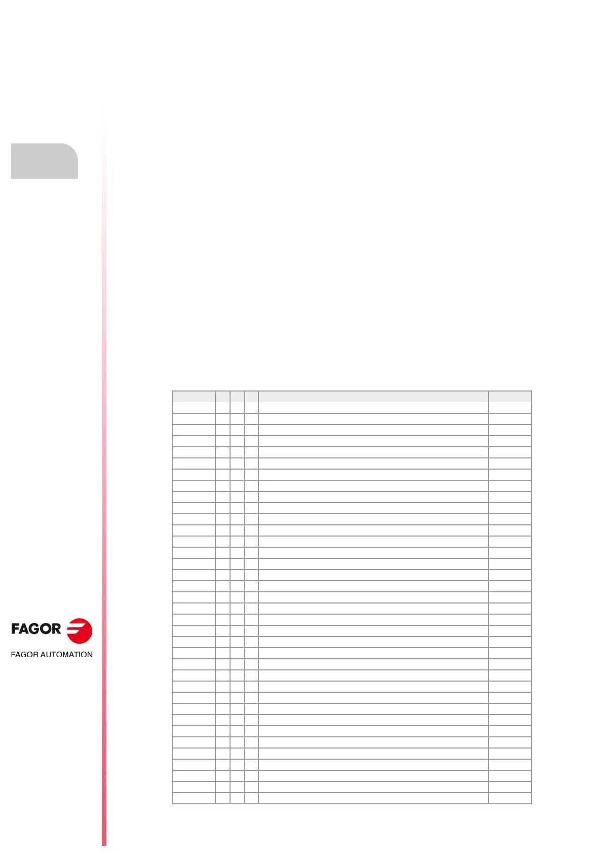
1.5 List of "G" functions.
The following tables show a list of "G" functions available at the CNC. The meaning of the
"M", "D" and "V" fields of the table is the following:
Next to each function, it indicates which chapter of this manual describes it; if no chapter
is indicated, the function is described in another manual.
·M· Modal function.
A modal function, once programmed, remains active until an incompatible "G" code is
programmed or an M02 or an M30 or until an EMERGENCY or a RESET is carried out or
the CNC is turned off and back on.
Those cases indicated with "!", mean the function remains active even after an M02, M30
or a reset and after the CNC is powered off and back on.
·D· Default function.
It is the function that is activated by default; in other words, the function assumed by the CNC
on power-up, after executing an M02 or M30 and after an EMERGENCY or a RESET.
Those cases indicated with "?" mean that the default quality of the function depends on the
settings of the CNC machine parameters.
·V· Displayed function.
The function is displayed in automatic and jog modes next to the current machining
conditions.
·M· Modal function. ·D· Default function.
·V· Displayed function.
Function M D V Meaning
G00 * ? * Rapid positioning. 8.1
G01 * ? * Linear interpolation. 8.2
G02 * * Clockwise circular (helical) interpolation. 8.3 / 8.6
G03 * * Counterclockwise circular (helical) interpolation. 8.3 / 8.6
G04 * Dwell. 12.1
G05 * ? * Controlled corner rounding (modal). 11.3
G06 * Arc center in absolute coordinates (not modal). 8.3.9
G07 * ? * Square corner (modal). 11.1
G08 * Arc tangent to previous path. 8.4
G09 * Arc defined by three points. 8.5
G10 * * Mirror image cancellation. 11.8
G11 * * Mirror image on X. 11.8
G12 * * Mirror image on Y. 11.8
G13 * * Mirror image on Z. 11.8
G14 * * Mirror image in the programmed directions. 11.8
G17 * ? * Main plane X-Y, and longitudinal axis Z. 4.2
G18 * ? * Main plane Z-X, and longitudinal axis Y. 4.2
G19 * * Main plane Y-Z, and longitudinal axis X. 4.2
G20 * * Main plane by two directions and longitudinal axis. 4.3
G30 * Polar origin preset. 5.7
G31 * Temporary polar origin shift to the center of arc. 8.3.8
G33 * * Electronic threading with constant pitch. 10.1
G34 * * Electronic threading with variable pitch. 10.2
G36 * Automatic radius blend. 11.4
G37 * Tangential entry. 11.6
G38 * Tangential exit. 11.7
G39 * Automatic chamfer blend. 11.5
G40 * * Cancellation of tool radius compensation. 13.1
G41 * * Left-hand tool radius compensation. 13.1
G42 * * Right-hand tool radius compensation. 13.1
G45 Turn tangential control on and off. 18.1
G50 * ? Semi-rounded corner. 11.2
G53 * Zero offset cancellation. 5.6
G54 ! * Absolute zero offset 1. 5.5
G55 ! * Absolute zero offset 2. 5.5
G56 ! * Absolute zero offset 3. 5.5