Using Auto-SYNC for Digital Input Connections
232 TIMS MVP™ Setup and Configuration Guide
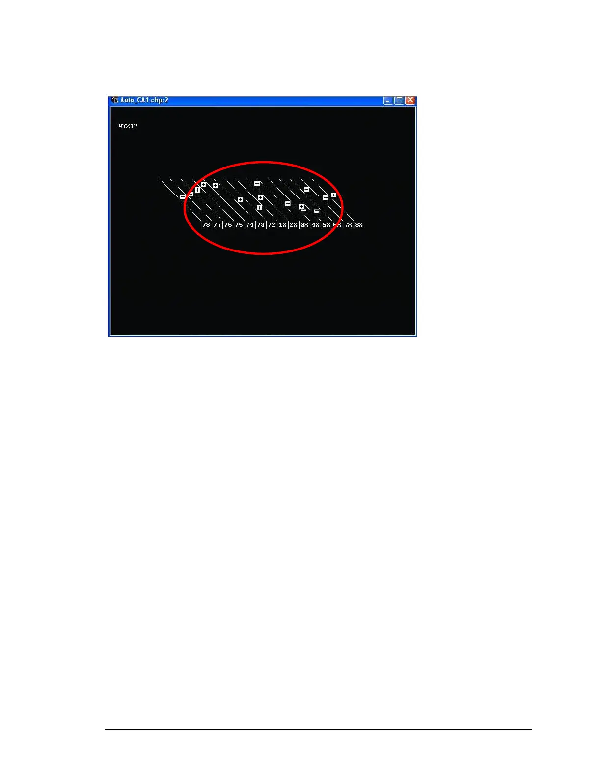
In the next example, the lines are broken and distorted. In order to adjust the image, change the
Field Polarity.
Figure 127: Example of video image with the improper Field Polarity setting
Tips:
Field Polarity
Fields are jagged in interlaced image – select Odd Field Up
Vertical Sync Type
Flagging at the top of the image – select Block as source
Miscellaneous Information
▪ One frame is one screen of visible data
▪ A frame of data contains visible AND non-displayed information, image blanking and
synchronization
▪ Interlaced signals are comprised of an Odd and Even field of separate Odd and Even
lines
▪ Two fields comprise a frame
▪ Non-interlaced, also called progressive scan, is one frame of sequential lines
▪ Fields must be paired properly and “ordered” properly