4-2.1 Basic FM Receiver Testing Setup
Refer to figure 4-2. Connect the analyzer's RF
I/O port to the radio antenna connector. Connect
the radio audio output to VERT/SINAD port of
the analyzer.
CAUTION
With some radios, grounding the speaker
leads will damage the audio circuitry. Use
isolation techniques on these radios.
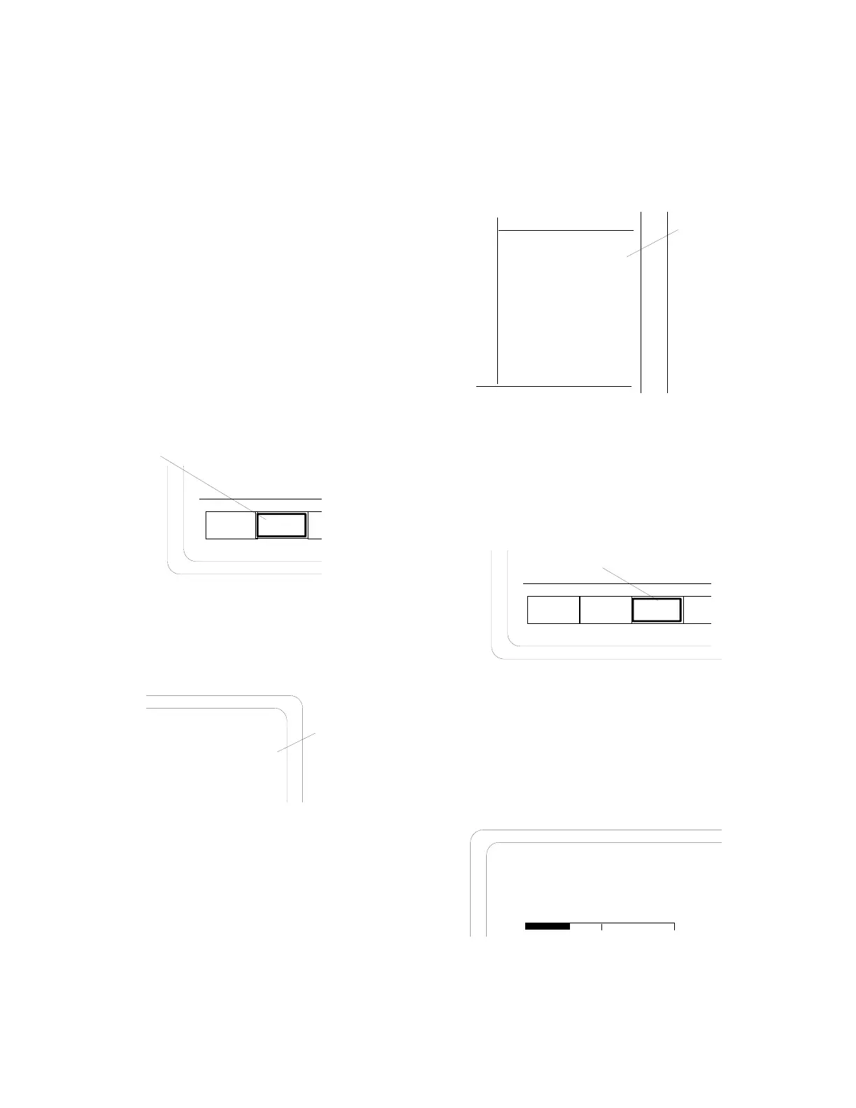
1. With the cursor located within the RF
Control zone (refer to paragraph 3-2), press
the
GEN softkey to place the analyzer into
its Generator mode of operation.
MON GEN
DUPLEX
Generator Mode
Softkey
2. Within the RF Control zone, set as follows:
RF Control:
Preset: - - B/W: NB
GENERATE
Freq:
Output Level:
-112 dB
816.5000 MHz
Mon RF In: RF I/O
Modulation Type:
FM
Receiver
Frequency
NOTE
For setup and distortion measurements, set
output level to at least 30 dB above sensitivity
threshold (-80 dBm recommended).
3. Within the Audio Control zone, set as
follows:
Mod Sum: 0.00 kHz
Fixed 1kHz:
Synth: 3.00 kHz
3 kHz
Format Sel:
DPL
Code
021
DTMF: 0.00 kHz
Code: 1234567890#ABCD
External: 0.00 kHz
Set to 60% of
System Deviation
~
x
x
x
4. With the cursor located within the Display
Control zone, press the AC VOLTS softkey
to display the ac voltmeter:
DC
VOLTS
RF
DISPLAY
AC Meter
RF
SCAN
AC
VOLTS
5. Adjust the radio for rated power output by
computing voltage needed for rated power
with load resistor/speaker in use, and setting
the radio volume to produce required
voltage.
Meter: AC VOLTMETER
Range: AUTO
3.50 VAC
0
10
-59.9 dBm
70
 Loading...