voltage difference between the two marker
positions.
T
This key selection provides markers that are
vertically located to permit relative readings
along the scope horizontal axis. The display
adjacent to the “Mrk:” field shows the relative
horizontal deflection between the two marker
positions in units of time.
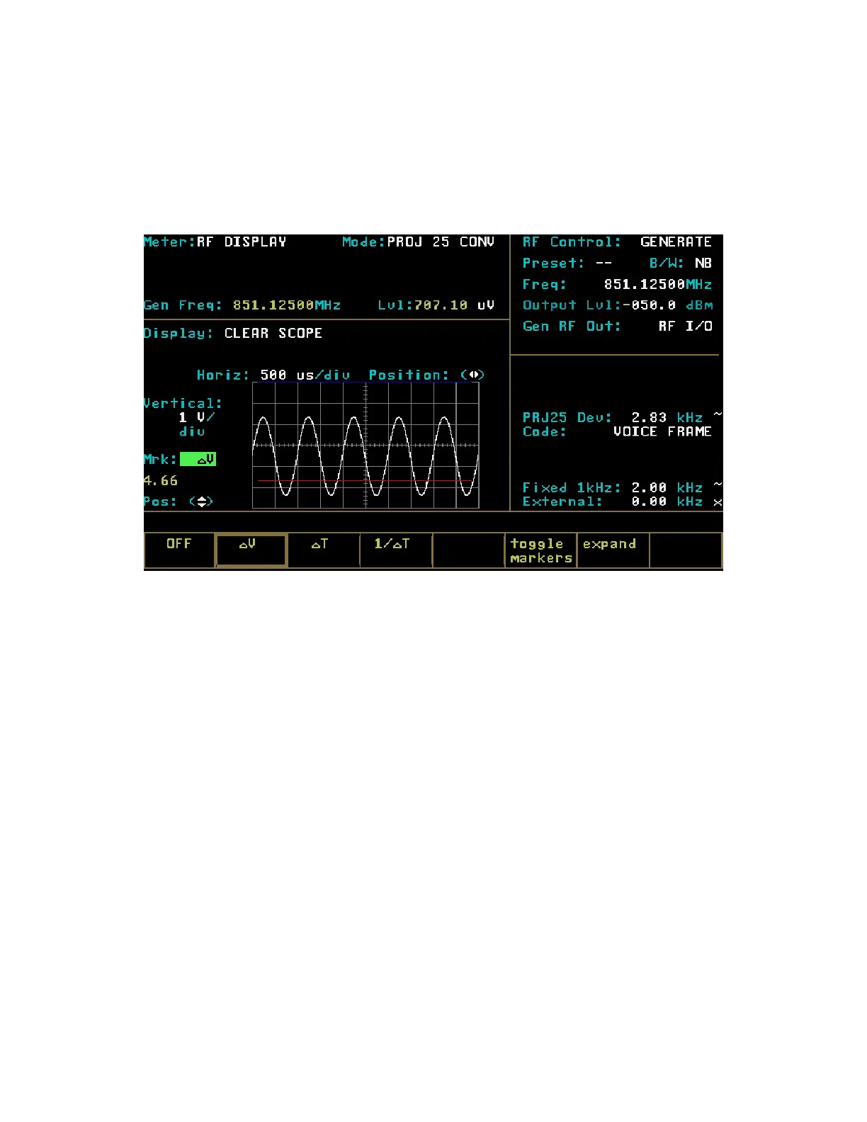
Figure 21-18. Clear Scope Markers
1/
T
This softkey selection provides markers that are
also vertically located to permit relative
readings along the scope horizontal axis. This
selection, however, inverts the time reading and
displays the relative difference in terms of
frequency.
21-10.2.2 Generate Mode
In Generate m
ode, the CLEAR SCOPE display
shows the generated analog audio signal. The
CLEAR SCOPE operational controls are the same
as those described for the CLEAR SCOPE in
Monitor mode.
21-10.3 Voice Frame Decode
The Voice Fram
e display is used to decode and
view the received embedded data in the link control
frame of Project 25 transmissions.
21-10.3.1 Embedded Signaling
The Project 25 provides a user display of decoded
embedded signaling (Figure 21-19). It saves the
last 30 frames of information on a first-in, first-out
(FIFO) basis. User controls are provided to start
and stop the data decoding process and to select a
specific frame for display.
To monitor the received embedded, voice frame
data, move cursor to the RF Control zone. Set the
fields as follows:
RF Control: Monitor
Freq: (same as transmitting unit)
B/W: NB
Attenuation: 0 db
Move the cursor to the Display Zone. Place cursor
in the “Display:” field and press VOICE FRAME
softkey. Press the decode start softkey to select
278
 Loading...