Home
General Dynamics
Measuring Instruments
R2600 Series
General Dynamics R2600 Series User Manual
5
of 1
of 1 rating
402 pages
Give review
Manual
Specs
To Next Page
To Next Page
To Previous Page
To Previous Page
Loading...
14-10
AUDIO/BER BASEBAND OUTPUT
GENERATION
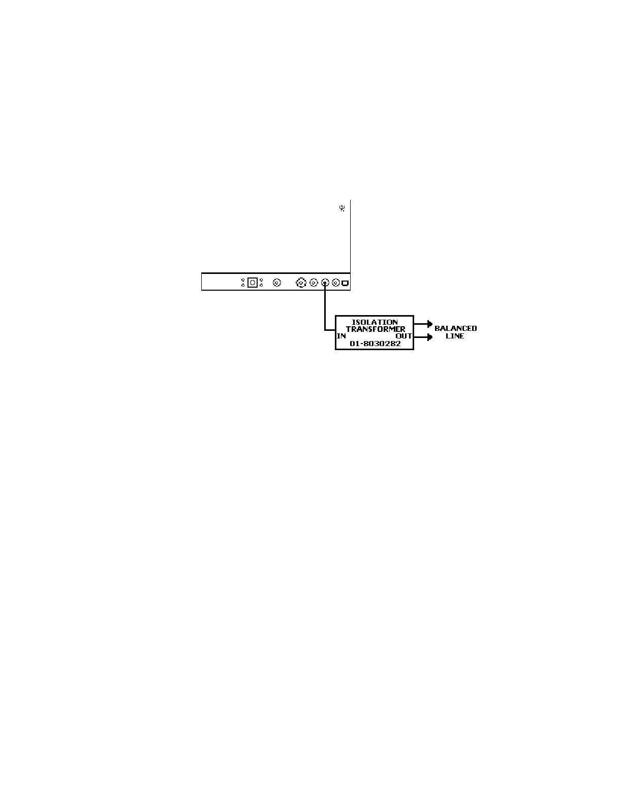
The baseband output is available at the MOD
OUT connector during normal SECURENET
Audio transmission. Use isolation
transformer 01-80302E82 to connect from the
MOD OUT connector to a 600-ohm balanced
line. Make the conn
ection as shown in
figure 14-10.
Figure 14-10. Audio/BER Baseband Output Generation
205
250
252
Table of Contents
Topic Page
4
Table of Contents
4
Topic Page
5
Securenet Option Operating Instructions
19
Astro Option Operating Instructions
24
List of Figures
36
Limited Warranty
43
Software License Agreement
44
Service Locations
45
1-2.1 Grounding the Analyzer
47
1-2.2 Unit Is Live When Plugged in
47
1-2.3 Keep Away from Live Circuits
47
Introduction
47
Safety Summary
47
Scope of Manual
47
1-2.2 das Gerät Steht Auch in Ausgeschaltetem Zustand unter Spannung
48
1-2.3 Vorsicht vor Spannungsführenden Teilen
48
Sicherheitshinweise
48
1-3.2 DC Power Source
49
1-3.3 Maximum DVM Input Voltages
49
Betrieb mit Gleichspannung
50
Betriebsspannung
50
Gefahrenhinweise
50
Maximale Eingangsspannung des Digitalvoltmeters
50
Table 1. Operator Replaceable Fuses
51
Table 2. Internal Fuses
51
1-3.4 Ersatz von Sicherungen
52
Tabelle 1. Sicherungen, die vom Benutzer Gewechselt werden können
52
Tabelle 2. Interne Sicherungen
52
1-6.2 Initial Set-Up
53
Installation
53
Replacement Parts Orders
53
Service
53
1-3.5 Sonstige Vorsichtsmaßnahmen
54
1-3.6 Ersatz und Entsorgung von Akkus
54
1-3.7 Reinigung
54
1-6.1 Verpackung
54
1-6.2 Erste Inbetriebnahme
54
Ersatzteil Bestellungen
54
Installation
54
Kundendienst
54
1-6.3 Battery Pack Operation
55
Figure 1-1. 115 VAC/230 VAC Selection Switch
55
1-6.3 Betrieb mit Akkusatz
56
Abb. 1-1. Spannungswähler für 115 / 220 VAC
56
1-6.4 Battery Pack Installation
57
Figure 1-2. Battery Pack Installation
57
1-6.4 Installation des Akkusatzes
58
Abb. 1-2. Installation des Akkusatzes
58
Figure 2-1. Front Panel Controls, Indicators, and Connectors
60
Figure 2-2. Side, Rear, and Bottom Panels
61
3-2.1 Remote Operation
65
Basic Operation
65
General
65
Operating Instructions
65
Figure 3-1. Screen Zone Arrangement
66
3-2.2 Expanded Display
67
3-2.2.1 Spectrum Analyzer, Scope Waveforms or Bargraph Display
67
3-2.2.2 Display Tables
67
3-2.2.3 Dedicated Keys
67
Help
67
Figure 3-2. System Help
68
Figure 3-3. RF Overtemperature Warning Message
69
Warnings
69
3-5.1 MONITOR Mode
70
Figure 3-4. Monitor Mode
70
Primary Operating Modes
70
3-5.1.1 Phase Modulation
71
3-5.2 GENERATE Mode
72
Figure 3-5. Phase Modulation
72
Figure 3-6. Generate Mode
72
3-5.3 DUPLEX Mode
74
Figure 3-7. Duplex Mode
74
3-5.4 SWEEP GENERATE Mode
76
Figure 3-8. Sweep Generator Mode
76
3-5.5 TRACKING GENERATOR Mode (if Equipped)
78
Figure 3-9. Tracking Generator Mode
78
3-6.2 Synth
80
Audio/Modulation Synthesizer
80
Fixed 1 Khz
80
Figure 3-10. PL Format Selection
81
Figure 3-11. General Sequence Mode Select
83
3-7.1 Meter
84
3-7.1.1 RF Display
84
Dtmf
84
External
84
Meter and Display
84
Figure 3-12. RF Display Zone
85
3-7.1.2 RF Scan
86
Figure 3-13. RF Control Zone; Scan Mode
86
Figure 3-14. Digital Voltmeter Screens
88
3-7.1.5 SINAD Meter
89
3-7.1.6 Counter and Decoding Functions
89
Figure 3-15. Frequency Counter
90
3-7.1.7 CABLE FAULT (if Equipped)
91
Figure 3-16. Cable Fault Screen
91
3-7.1.8 General Seq Decode
92
3-7.1.9 Preset Scan (if Equipped)
93
Figure 3-17. Preset Scan
93
3-7.2.1 Spectrum Analyzer
95
Display
95
Figure 3-18. Spectrum Analyzer
95
Figure 3-19. Spectrum Analyzer Markers (Option)
97
3-7.2.2 Modulation Scope
98
Figure 3-20. Modulation Scope
98
Figure 3-21. Modulation Scope Markers (Option)
100
3-7.2.3 Ext'l Scope
101
3-7.2.4 Sweep Generate
101
3-7.2.5 Bar Graphs
101
Figure 3-22. Bar Graphs
102
3-7.2.6 Tracking Generator (if Equipped)
103
3-8.1 Audio Monitor
103
3-8.2 Calibration
103
3-8.3 Print Function
103
Other Functions
103
3-8.4 Special Functions Menu
104
Figure 3-23. Special Functions Menu
104
3-8.4.1 Special Function Selection
106
3-8.5 Memory Screens
106
Figure 3-24. Memory Screens
107
3-8.6 Test Setups (if Equipped)
108
Figure 3-25. Memory Screen with Full Test Setups Option
109
Basic Fm Transmitte Testing
110
Figure 4-1. Basic FM Transmitter Testing Setup
110
Basic FM Transmitter Testing Setup
111
Transmit Power, Frequency, and Frequency Deviation Measurements
111
Modulation Measurements
112
4-1.4 Off-The-Air Measurements
114
Basic Fm Receiver Testing
115
Figure 4-2. Basic FM Receiver Testing Setup
115
Basic FM Receiver Testing Setup
116
4-2.2 Receiver Distortion Measurement
117
SINAD Measurement
117
4-2.4 Modulation Acceptance Bandwidth
118
4-2.5 Receiver Sensitivity Testing (20 Db Quieting)
119
4-2.6 Squelch Sensitivity Test
120
4-3.1 Overview
122
4-3.2 Measuring Fault Distance
122
CABLE TESTING (if Equipped)
122
Figure 4-3. Basic Cable Testing Setup
122
Figure 4-4. Tone Remote Testing Setup
125
Tone Remote Testing
125
4-4.2 Checking for Proper Tone Remote Operation
126
Tone Remote Testing Setup
126
Analyzer Setup for Printing
127
Capabilities
129
Introduction
129
What Is Trunking
130
5-3.1 Trunk Signaling Types
131
6-2 Test Setup
133
Connecting a Radio
133
Introduction
133
Figure 6-1. Trunked Radio Test Setup
134
6-4 General Operation
135
Figure 6-2. Trunking Analyzer Option Screen
135
Trunking Analyzer Software Version Screen
135
6-4.1 Access to Standard System Test Screens During Trunking Testing
136
6-4.2 Spectrum Analyzer Dispersion Limit While in Trunked Test Mode
136
6-4.3 Remote Operation
136
6-5 Accessing Trunk Mode
137
6-6 Radio Initiated Trunking
137
6-6.1 Radio Initiated Dispatch Trunk I Testing
137
Figure 6-3. Trunk Mode Screen - Radio Initiated Trunk I
137
Figure 6-4. Dispatch Test Screen - Radio Initiated Trunk I Signaling
138
6-6.2 Rf Zone
139
Table 6-1. Available Transmit Frequency Ranges and Channel Plans (800 Mhz Selection)
140
Table 6-2. Available Transmit Frequency Ranges and Channel Plans (800 Mhz Int'l)
140
Table 6-3. Available Transmit Frequency Ranges and Channel Plans (800 Mhz JSMR)
140
Table 6-4. Available Transmit Frequency Ranges and Channel Plans (900 Mhz Selection)
141
6-6.3 Radio Initiated Dispatch Trunk IEP II Testing
143
6-6.4 Radio Initiated Dispatch Trunk II Testing
143
Figure 6-5. Dispatch Test Screen - Radio Initiated Trunk I EP II Signaling
143
Figure 6-6. Dispatch Test Screen - Radio Init Trunk II Signaling
144
6-6.5 Radio Initiated Dispatch Trunk II Testing Testing the Auto Affiliation Feature
145
6-7 System Initiated Trunking
146
6-7.1 System Initiated Dispatch Trunk I Signaling
146
6-7.2 System Initiated Dispatch Trunk IEP II Signaling
147
Figure 6-7. Dispatch Test Screen - System Init Trunk I and Trunk I EP II Signaling
147
6-7.3 System Initiated Dispatch Trunk II Signaling
148
Figure 6-8. Dispatch Test Screen - System Init Trunk II Signaling
148
6-8 Radio Configuration
149
6-8.1 Radio Configuration Trunk I and Trunk I EP II
149
Figure 6-9. Radio Configuration Screen - Trunk I and Trunk I EP II
149
Table 6-5. Transmit Deviation Selections
150
6-8.2 Radio Configuration Trunk II
151
Figure 6-10. Radio Configuration Screen - Trunk II
151
6-8.2.1 Trunk II VHF/UHF Radio Configuration
152
Table 6-6 Trunking Frequency Information Example
153
Figure 6-11. Radio Configuration Screen - Trunk II VHF/UHF Example
154
7-1 Basic Trunked Radio Testing
155
7-2 Dispatch Testing
155
7-2.1 Radio Initiated Dispatch Test Sequence, Trunk I and Trunk I EP II Signaling
155
Table 7-1. Trunk I Signaling Events Radio Initiated Dispatch Testing
156
Table 7-2. Trunk I EP II Signaling Events Radio Initiated Dispatch Testing
156
7-2.2 Radio Initiated Dispatch Test Sequence, Trunk II Signaling
157
Table 7-3. Trunk II Signaling Events Radio Initiated Dispatch Testing Without Auto Affiliation
158
Table 7-4. Trunk II Signaling Events Radio Initiated Dispatch Testing with Auto Affiliation
158
7-2.3 System Initiated Dispatch Test Sequence, Trunk I and Trunk I EP II Signaling
159
Table 7-5. Trunk I Signaling Events System Initiated Dispatch Testing
160
Table 7-6. Trunk I EP II Signaling Events System Initiated Dispatch Testing
160
7-2.4 System Initiated Dispatch Test Sequence, Trunk II Signaling
161
Table 7-7. Trunk II Signaling Events System Initiated Dispatch Testing Without Auto Affiliation
162
Table 7-8. Trunk II Signaling Events System Initiated Dispatch Testing with Auto Affiliation
162
7-3 Phone Interconnect Testing
163
Radio Initiated Phone Interconnect Test Sequence
163
Trunk I and Trunk I EP II Signaling
163
Table 7-10. Trunk I EP II Signaling Events Radio Initiated Phone Interconnect Testing
164
Table 7-9. Trunk I Signaling Events Radio Initiated Phone Interconnect Testing
164
7-3.2 Radio Initiated Phone Interconnect Test Sequence, Trunk II Signaling
165
Table 7-11. Trunk II Signaling Events Radio Initiated Phone Interconnect Testing Without Auto Affiliation
166
Table 7-12. Trunk II Signaling Events Radio Initiated Phone Interconnect Testing with Auto Affiliation
166
System Initiated Phone Interconnect Test Sequence
167
Trunk I and Trunk I EP II Signaling
167
Table 7-13. Trunk I Signaling Events System Initiated Phone Interconnect Testing
168
Table 7-14. Trunk I EP II Signaling Events System Initiated Phone Interconnect Testing
168
7-3.4 System Initiated Phone Interconnect Test Sequence, Trunk II
169
Table 7-15. Trunk II Signaling Events System Initiated Phone Interconnect Testing Without Auto Affiliation
170
Table 7-16. Trunk II Signaling Events System Initiated Phone Interconnect Testing with Auto Affiliation
170
Call Alert Testing
171
Radio Initiated Call Alert Test Sequence, Trunk I and Trunk I EP II Signaling
171
Table 3-17. Trunk I and Trunk I EP II Signal Events Radio Initiated Call Alert Testing
171
7-4.2 Radio Initiated Call Alert Test Sequence, Trunk II Signaling
172
Table 7-18. Trunk II Signaling Events Radio Initiated Call Alert Testing Without Auto Affiliation
173
Table 7-19. Trunk II Signaling Events Radio Initiated Call Alert Testing with Auto Affiliation
173
System Initiated Call Alert Test Sequence, Trunk I and Trunk I EP II Signaling
174
Table 7-20. Trunk I and Trunk I EP II Signaling Events System Initiated Call Alert Testing
175
7-4.4 System Initiated Call Alert Test Sequence, Trunk II Signaling
176
Table 7-21. Trunk II Signaling Events System Initiated Call Alert Testing Without Auto Affiliation
177
Table 7-22. Trunk II Signaling Events System Initiated Call Alert Testing with Auto Affiliation
177
7-5 Failsoft Testing
178
7-5.1 System Initiated Failsoft Test Sequence
178
Connecting a Radio
181
Introduction
181
Test Setup
181
Figure 9-1. Trunked Radio Test Setup
182
Figure 9-2. Trunking Analyzer Option Screen
183
Trunking Analyzer Software Version Screen
183
9-4.1 Access to Standard System Test Screens During Trunking Testing
184
9-4.2 Spectrum Analyzer Dispersion Limit While in Trunked Test Mode
184
9-4.3 Remote Operation
184
General Operation
184
9-6.1 Radio Initiated Dispatch Astro Testing
185
Accessing Trunk Mode
185
Figure 9-3. Trunk Mode Screen
185
Radio Initiated Trunking
185
Figure 9-4. Dispatch Test Screen Radio Initiated Astro Signaling
186
9-6.2 Testing the Auto Affiliation Feature
187
9-6.3 Rf Zone
187
9-6.4 Audio Zone
188
System Initiated Trunking
189
Table 9-1. Available Transmit Frequency Ranges and Channel Plans (800 Mhz Selection)
189
9-7.1 System Initiated Dispatch Astro Signaling
190
Figure 9-5. Dispatch Test Screen System Initiated Astro Signaling
190
9-7.2 Display Zone, Rf Zone, and Audio Zone
191
Figure 9-6. Radio Configuration Screen-Astro
191
Radio Configuration
191
Table 9-2. Transmit Deviation Selections
192
10-2.1 Radio Initiated Dispatch Test, Astro Signaling
193
Basic Trunked Radio Testing
193
Dispatch Testing
193
Table 10-1. Astro Signaling Events Radio Initiated Dispatch Testing Without Auto Affiliation
194
10-2.2 System Initiated Dispatch Test Astro Signaling
195
Table 10-2. Astro Signaling Events Radio Initiated Dispatch Testing with Auto Affiliation
195
Table 10-3. Astro Signaling Events System Initiated Dispatch Testing Without Auto Affiliation
196
10-3.1 Radio Initiated Call Alert Test, Astro Signaling
197
Call Alert Testing
197
Table 10-4. Astro Signaling Events System Initiated Testing with Auto Affiliation
197
Table 10-5. Astro Signaling Events Radio Initiated Call Alert Testing Without Auto Affiliation
198
Table 10-6. Astro Signaling Events Radio Initiated Call Alert Testing with Auto Affiliation
198
10-3.2 System Initiated Call Alert Test, Astro Signaling
199
Table 10-7. Astro Signaling Events System Initiated Call Alert Testing Without Auto Affiliation
200
Table 10-8. Astro Signaling Events System Initiated Call Alert Testing with Auto Affiliation
200
10-4.1 Radio or System Initiated Failsoft Test, Astro Signaling
201
Failsoft Testing
201
Figure 11-1. R-2670 with SECURENET Option Housing
205
13-1 Introduction
209
13-2 Software Version Screen
210
Figure 13-1. SECURENET Version Screen
210
13-3 Basic Operation
211
13-3.1 Display Screens
211
Figure 13-2. SECURENET Options Screen
211
13-3.2 Manual Operation
212
13-3.3 Expanded Display
212
13-3.4 Dedicated Keys
212
Figure 13-3. Screen Zone Arrangement
212
13-3.5 Remote Operation
213
13-3.6 Help
213
13-4 Encryption Capabilities
213
13-5 Test Setup
214
13-5.1 Connecting a Radio
214
Figure 13-4. Radio to Analyzer Test Setup
214
13-6 Accessing Securenet Mode
215
Figure 13-5. SECURENET Mode Screen
215
13-7 Securenet Encryption Set up
216
13-7.1 SET up Encrypter Display
216
13-7.1.1 Algorithm Select
216
Figure 13-6. SET up Display Screen
216
13-7.1.2 Key Type
217
Figure 13-7. Algorithm Select Display
217
Figure 13-8. Test Key Programming Display
218
Figure 13-9. External Key Programming Display
218
13-7.1.3 Encrypt Self Test
219
13-7.2 Programming with Test Key
219
13-7.3 Programming with External Key
219
13-7.3.1 Connecting the Key Inserter
219
13-7.3.2 Loading External Key
219
13-7.3.3 Erasing External Key
220
13-8.1 MONITOR Mode
221
Figure 13-10. Monitor Mode - RF Zone
221
Securenet Rf Operating Modes
221
13-8.2 GENERATE Mode
222
Figure 13-11. Generate Mode - RF Zone
223
13-8.3 DUPLEX Mode
224
Figure 13-12. Duplex Mode - Display Zone
225
13-9.1 Modulation Sources
226
13-9.1.1 Fixed 1 Khz
226
13-9.1.2 External
226
13-9.2 Voice Encode
226
13-9.2.1 Monitor Mode
226
Securenet Audio/Modulation Control
226
13-9.2.2 Generate Mode
227
Figure 13-13. SECURENET Audio Zone - Voice Generate Mode
228
13-9.3 BER Encode
229
13-9.3.1 Monitor Mode
229
13-9.3.2 Generate Mode
229
13-9.3.3 Duplex Mode
229
Figure 13-14. SECURENET Audio Zone - BER Generate Mode
229
13-10.1 SECURENET BER Meter
230
Figure 13-15. SECURENET BER Meter
230
Securenet Meter and Display Control
230
13-10.2 CLEAR SCOPE Display
231
13-10.2.1 Monitor Mode
231
13-10.2
233
13-10.2.3 Duplex Mode
233
Figure 13-16. SECURENET CLEAR SCOPE Display
233
Figure 13-17. CLEAR SCOPE Markers
234
13-10.3 EOM Signaling Tone
235
Figure 13-18. EOM Received Message
235
14-1.1 Setting the Deviation Level
237
14-1.2 Monitor Mode Testing
237
14.1 Basic SECURENET Radio Testing
237
14-1.3 Generate Mode Testing
238
14-2.1 Radio in BER Test Mode
238
BER TESTING the RADIO RECEIVER (Generate Mode)
238
14-3.1 Radio in BER Test Mode
239
BER TESTING the RADIO TRANSMITTER (Monitor Mode)
239
Figure 14-1. Radio (BER Test Mode) Audio Zone
240
Figure 14-2. Radio (BER Test Mode) BER Meter Sample
240
Ber Testing Using Duplex Mode
241
Figure 14-3. Transmit BER
241
14-4.1 Radios Without BER Test Capability
242
Figure 14-4. Receive BER
242
14-4.2 Radios with BER Test Capability and Repeaters
243
Voice Pattern Testing in Generate Mode
243
Figure 14-5. Basic FM Receiver Testing Setup
244
Voice Pattern Testing in Monitor Mode
244
Figure 14-6. Basic FM Transmitter Testing Setup
245
Measuring Received Audio with Clear Scope
246
Figure 14-7. SECURENET CLEAR SCOPE Display of Recovered Audio
247
Measuring Transmitted Audio with Clear Scope
247
Figure 14-8. SECURENET CLEAR SCOPE Display of Output Modulation
249
Audio/Ber Baseband Input Monitoring
250
Figure 14-9. Audio/Ber Baseband Input Monitoring
250
Audio/Ber Baseband Output Generation
251
Figure 14-10. Audio/Ber Baseband Output Generation
251
Figure 15-1. ASTRO Option Housing
255
17-1 Introduction
259
17-2 Software Version Screen
260
Figure 17-1. ASTRO Version Screen
260
17-3 Basic Operation
261
17-3.1 Display Screens
261
Figure 17-2. ASTRO Options Screen
261
17-3.2 Manual Operation
262
17-3.3 Expanded Display
262
17-3.4 Dedicated Keys
262
Figure 17-3. Screen Zone Arrangement
262
17-3.5 Remote Operation
263
17-3.6 HELP Key
263
17-4 Encryption Capabilities
263
17-5 Test Setup
263
17-5.1 Connecting a Radio
263
Figure 17-4. Radio to Analyzer Test Setup
264
17-6 Accessing Astro Mode
265
Figure 17-5. ASTRO Mode Screen
265
17-7 Astro Encryption Set up
266
17-7.1 SET up Encryption Display
266
17-7.1.1 Encrypt
266
17-7.1.2 Algorithm Select
266
Figure 17-6. SET up Display Screen
266
Figure 17-7. Encryption Select Display
267
17-7.1.3 Key Type
268
Figure 17-8. Algorithm Select Display
268
Figure 17-9. Test Key Programming Display
269
17-7.1.4 Encrypt Self Test
270
17-7.2 Using the Test Key
270
17-7.3 Programming with External Key
270
Figure 17-10. External Key Programming Display
270
17-7.3.1 Connecting the KVL
271
17-7.3.2 Loading External Key
271
17-7.3.3 Erasing External Key
271
17-8 Astro Rf Operating Modes
271
17-8.1 MONITOR Mode
271
Figure 17-11. Monitor Mode - RF Zone
272
17-8.2 GENERATE Mode
273
Figure 17-12. Generate Mode - RF Zone
273
17-8.3 DUPLEX Mode
274
Astro Audio/Modulation Control
275
Figure 17-13. Duplex Mode - Display Zone
275
17-9.1 Modulation Sources
276
17-9.1.1 Fixed 1 Khz
276
17-9.1.2 External
276
17-9.2 Voice Encode
276
17-9.2.1 Monitor Mode
276
17-9.2.2 Generate Mode
276
Figure 17-14. ASTRO Audio Zone - Voice Generate Mode
277
Figure 17-15. Voice Frame Encode - Generate
278
Voice Frame Embedded Signaling (Generate)
278
17-10.1 Monitor Mode
279
17-10.2 Generate Mode
279
Ber
279
Table 17-1. Encoded Embedded Signal Default Values
279
17-10.3 Duplex Mode
280
Figure 17-16. ASTRO Audio Zone - BER Generate Mode
280
Astro Meter and Display Control
281
Figure 17-17. ASTRO BER Meter
281
17-11.1 ASTRO BER Meter
282
17-11.1.1 Enabling the BER Test
282
17-11.1.2 Resetting the BER Test
282
17-11.2 CLEAR SCOPE Display
282
17-11.2.1 Monitor Mode
282
Figure 17-18. ASTRO CLEAR SCOPE Display
283
17-10.2.3 Generate Mode
284
17-10.2.4 Duplex Mode
284
17-11.2.2 Marker (if Equipped)
284
Figure 17-19. CLEAR SCOPE Markers
284
17-11.3 Voice Frame Decode
285
17-11.3.1 Embedded Signaling
285
Figure 17-20. Voice Frame Decode Display
285
18-1.1 Monitor Mode Testing
287
18-1.2 Generate Mode Testing
287
18.1 Basic ASTRO Radio Testing
287
18-2 Astro Radio Transmit Tests
288
18-2.1 ASTRO Voice
288
18-2.2 ASTRO Embedded Data
288
18-3 Astro Radio Receive Tests
289
BER TESTING the RADIO RECEIVER (Generate Mode)
289
BER TESTING the RADIO TRANSMITTER (Monitor Mode)
290
Figure 18-1. Radio (BER Test Mode) Audio Zone
291
Figure 18-2. Radio (BER Test Mode) BER Meter
291
Ber Testing Using Duplex Mode
292
Figure 18-3. Transmit BER
292
Figure 18-4. Receive BER
293
Monitoring Received Audio with Clear Scope
294
Radios with Ber Test Capability and Repeaters
294
Figure 18-5. ASTRO CLEAR SCOPE Display of Recovered Audio
296
Monitoring Transmitted Audio with Clear Scope
296
Figure 18-6. ASTRO CLEAR SCOPE Display of Output Modulation
298
Figure 19-1. Bottom of R2670
300
Figure 21-1. PROJ 25 Version Screen
304
Figure 21-2. PROJ 25 Options Screen
304
Figure 21-3. Screen Zone Arrangement
305
Figure 21-4. Radio to Analyzer Test Setup
307
Figure 21-5. PROJ 25 Mode Screen
308
Figure 21-6. SET up Display Screen
309
Figure 21-7. Encryption Select Display
309
Figure 21-8. Algorithm Select Display
310
Figure 21-9. Test Key Programming Display
311
Figure 21-10. External Key Programming Display
312
Figure 21-11. Monitor Mode-RF Zone
313
Figure 21-12. Generate Mode-RF Zone
314
Figure 21-13. PROJ 25 Audio Zone-Voice Generate Mode
316
Figure 21-14. Voice Frame Encode-Generate
318
Figure 21-15. PROJ 25 Audio Zone-BER Generate Mode
319
Figure 21-16. PROJ 25 BER Meter
321
Figure 21-17. PROJ 25 CONV Clear Scope Display
323
Figure 21-18. Clear Scope Markers
324
Figure 21-19. Voice Frame Decode Display
325
Figure 22-1. Radio (BER Test Mode) Audio Zone
329
Figure 22-2. Radio (BER Test Mode) BER Meter
331
Figure 22-3. PROJ 25 CLEAR SCOPE Display of Recovered Audio
333
Figure 22-4. PROJ 25 CLEAR SCOPE Display of Output Modulation
335
Figure 23-1. Bottom of R2670
337
Figure 24-1. PROJ 25 Version Screen
339
Figure 24-2. PROJ 25 Option Screen
339
Figure 24-3. Screen Zone Arrangement
340
Figure 24-4 PROJ 25 TRK Mode Screen
342
Figure 24-5 Registration Call Alert Meter Selection
343
Figure 24-6. PROJ 25 Trunk BASE Test Meter Selection
348
Figure 24-7. PROJ 25 Trunk BER Test Meter Selection
350
Figure 24-8. Test Setup
351
Figure 25-1. PROJ 25 CONV Mode Screen
352
Figure 25-2. SET up Display Screen
353
Figure 25-3. Encryption Select Display
354
Figure 25-4. Algorithm Select Display
354
Figure 25-5. Test Key Programming Display
356
Figure 25-6. External Key Programming Display
357
Table B-1. Standard DTMF TONES
364
Table B-2. DTMF Frequency Coding
364
Table B-3. Private-Line (PL) Codes
365
Table B-4. 5/6 Tone Paging Tones
367
Table B-5. DPL Standard Codes
367
Table B-6. Select V Frequencies
368
Figure D-1. Rear Panel DC Input Port
373
Table F-1. Trunk I Signaling Types
376
Table F-2. Trunk II Signaling Call Types
377
Table H-1. Test Sequence Code Description for ASTRO Trunking
382
Table I-1. ASTRO Signaling ISW Call Types
384
5
Based on 1 rating
Ask a question
Give review
Questions and Answers:
Need help?
Do you have a question about the General Dynamics R2600 Series and is the answer not in the manual?
Ask a question
General Dynamics R2600 Series Specifications
General
Brand
General Dynamics
Model
R2600 Series
Category
Measuring Instruments
Language
English
Related product manuals
General Dynamics R2670 Series
402 pages