76
4-3 CABLE TESTING (if equipped)
4-3.1 Overview
The analyzer cable fault test system can be used
to find the distance to a fault in a cable
under test such as an open or shorted connector, a
damaged (pinched) area of the cable, etc.
IN/OUT
GEN
OUT
VERT/SINAD
DIST/DVM
COUNTER IN
DEMOD
OUT
MOD
OUT
EXT
MOD
IN
1V
PK
REF
MIC
CABLE UNDER TEST
ANT
50 OHM TERMINATION
OR ANTENNA
RF INPUT
50 OHM RF TEE
(09-82578B01)
RF OUTPUT
RTL-4075A
RF DETECTOR
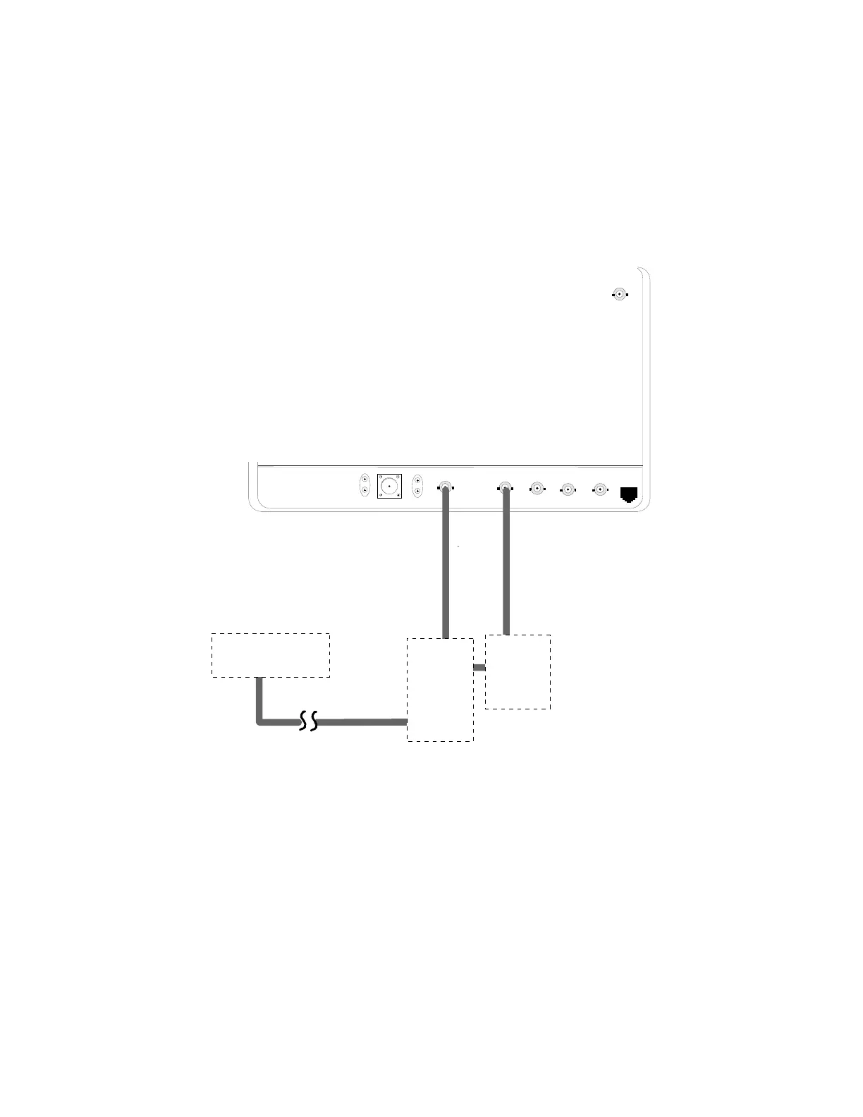
Figure 4-3. Basic Cable Testing Setup
4-3.2 Measuring Fault Distance
Refer to figure 4-3. Connect the output of the RF
Detector Probe (RTL-4075A) to the
VERT/SINAD connection of the R2600
Analyzer. Attach a 50 ohm Tee (09-82578B01)
to the GEN OUT/IN connection of the analyzer,
and connect the RF input of the detector probe to
the RF Tee. Connect the cable under test to the
RF Tee.
To measure fault distance, terminate the free end
of the cable with a 50 ohm load or the antenna
To measure cable length, leave the free end of the
cable open
 Loading...