appropriate time. Refer to Appendix F for a
description of the status thermometer signaling
events for each test sequence.
In addition to the information already on the screen,
the trunking analyzer calculates and displays the
connect tone frequency. After the analyzer displays
the connect tone frequency, it remains unchanged
for the rest of the test sequence.
The thermometer display progresses rapidly
through the signaling events and stops after the
Connect Tone Received on VC step. At this point,
the radio has sent a connect tone on the voice
channel. The connect tone stays on the voice
channel as long as the radio is keyed.
In testing a radio from Type II hybrid systems
where one signaling type is actually employed
while the radio ID information is mapped over to
the other signaling types ID format, the trunking
analyzer will always display the ID information per
the signaling type selected. EXAMPLE: If the radio
is actually signaled with Trunk II, yet its ID is
defined in terms is Trunk I, it must be tested as a
Trunk II radio and the displayed ID information
will be in the Trunk II format. For such hybrid
radios, verification of the mapped identify may be
done via Radio Service Software testing or by
manual conversion.
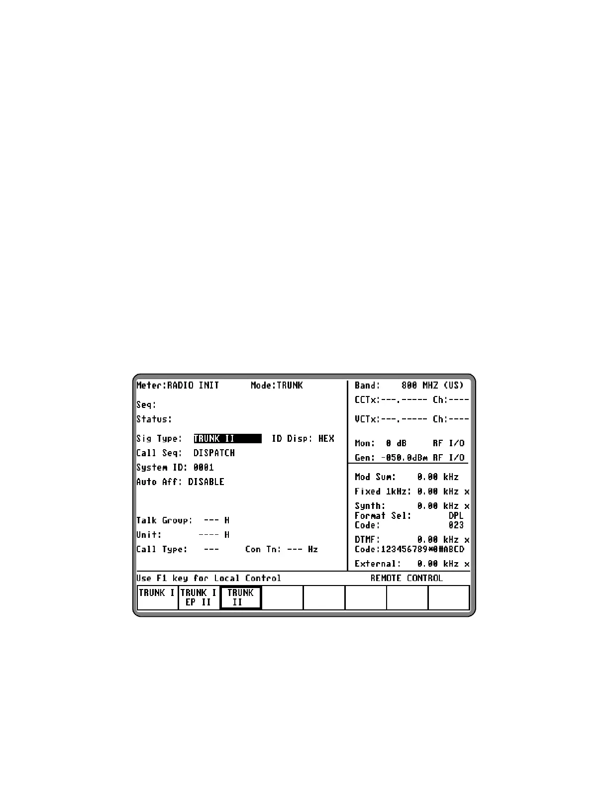
To set up testing, select the Trunk mode by placing
the cursor in the "Mode:" field in the Display Zone,
and selecting the TRUNK softkey. Place the cursor
in the "Meter:" field and press the softkey RADIO
INIT
to view current data and test status for a radio
initiated trunked test sequence. Within the Display
zone, place the cursor in the "Sig Type:" field and
press the softkey TRUNK II to select Trunk II
signaling. A screen similar to figure 2-6 appears.
Figure 6-6. Dispatch Test Screen – Radio Init Trunk II Signaling
98
 Loading...