The deviation switch with values of Off and
Continuous is located to the right of the deviation
level control field. Move the cursor to the switch
field and turn deviation on “~” or off “X” using the
softkeys.
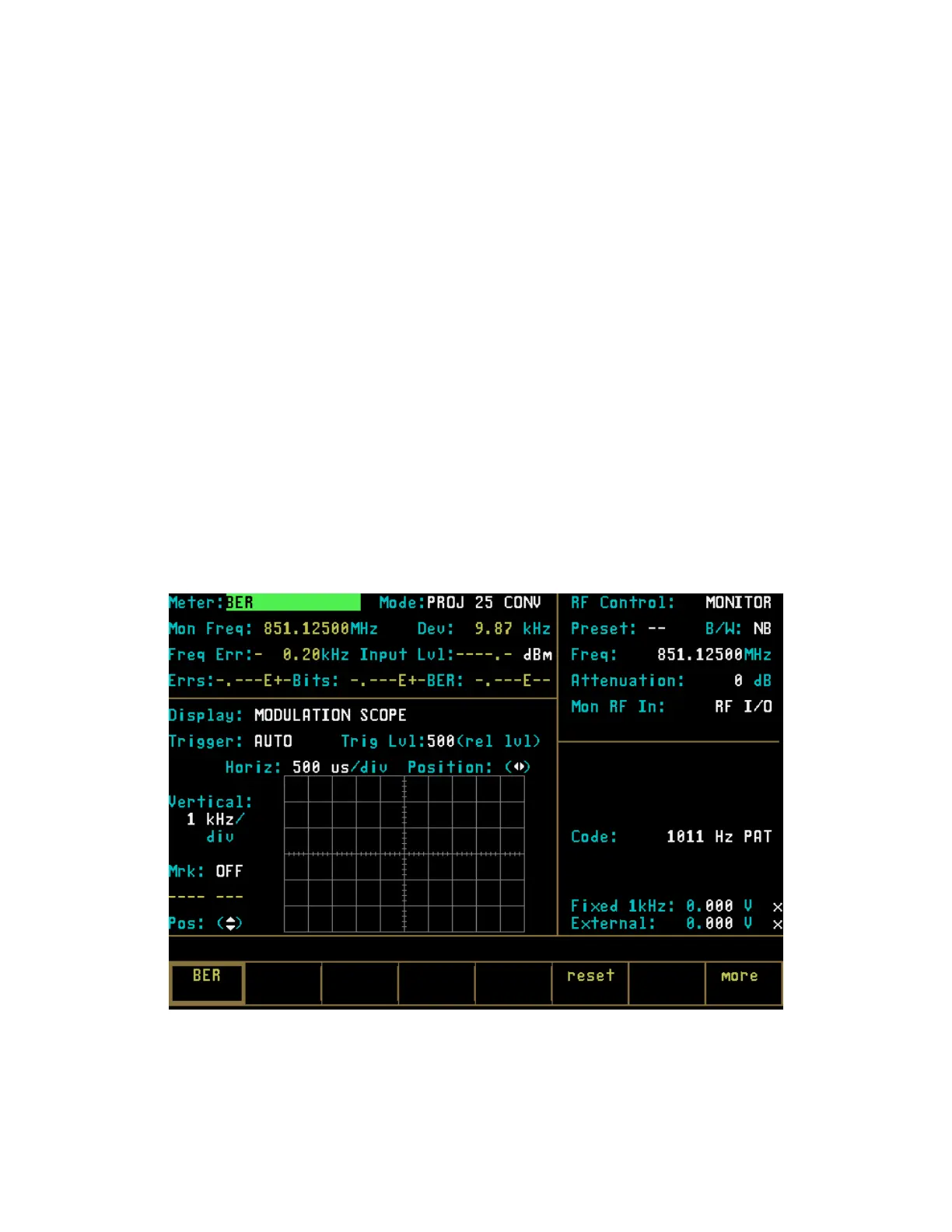
21-10.1 PROJ 25 CONV BER Meter
The BER Meter is used to verify the perform
ance
of test signals, generated by Project 25 radios. The
BER Meter provides display of bit error rate,
frequency error and input power level as well as
monitor frequency and deviation. An example of a
BER Meter is available only when Monitor “RF
Control:” mode has been selected.
21-10 PROJ 25 CONV METER AND DISPLAY
CONTROL
PROJ 25 CONV “Meter:” and “Display:” fields in
the Display Zone are similar to the standard mode.
Refer to Section 21-7 under the General Operation
tab in this manual for a general description of the
functionality of “Meter:” and “Display:” field
selections. To accommodate testing of Project 25
radio equipment, several additional selections have
been added for these fields. A BER meter is added
to the metering functions in the Display Zone.
VOICE FRAME, CLEAR SCOPE and SET UP
selections have been added to the display functions
in the Display Zone. The selections that have been
added are described in the following paragraphs.
To activate the BER test, set controls in the RF
Zone as follows:
RF Control: Monitor
Frequency: Same as radio transmit frequency
Attenuation: 0 dB
Mon RF In: RF I/O
The BER Meter is accessed by placing the cursor in
the Display Zone’s “Meter:” Field and pressing the
more softkey until the BER softkey is presented.
Selected the BER softkey to access the BER Meter
(Figure 21-16).
Figure 21-16. PROJ 25 CONV BER Meter
275
 Loading...