13-5 TEST SETUP
13-5.1 Connecting a Radio
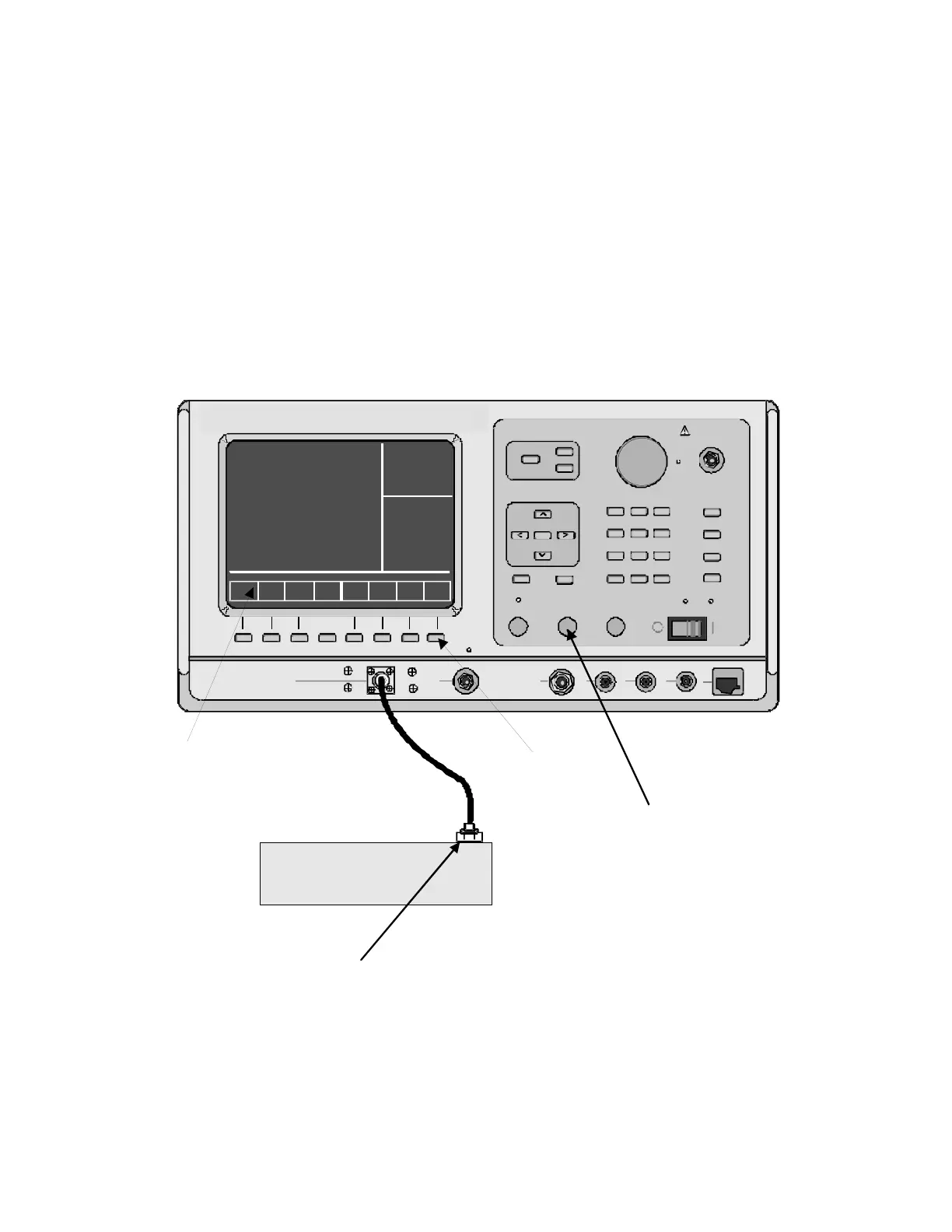
Use a 50-ohm BNC cable and an N to BNC
adaptor to connect from the RF I/O port of the
R2670 analyzer to the antenna port of the radio as
shown in figure 13-4.
168
CAUTION
Adjust the squelch to where the led indicator
for squelch just turns off or is closed. When
the signal from the radio is present, the
squelch LED will illuminate indicating that
squelch has been detected and there is a
signal present.
CAUTION
Observe the input power ratings and
warnings of the analyzer to insure that no
damage occurs to the analyzer.
Figure 13-4. Radio to Analyzer Test Setup
DISPLAY
RF
CONTROL
UDI
CONTROL
TUNING
MAX INPUT
0dBM
ANT
ON
POWER
DC
BRIGHT
7
89
456
23
ALT
0+/-
1
F1
SPF
PRT
CAL
VOLUMESQUELCH
CURSOR ZONE
CURSOR POSITION
DISP
RF
AUD
TAB
HELP MEM
RF IN/OUT
CAUTI ON
125W MAX
GEN
OUT
CAUTI ON
DO NOT
INPUT
POWER
VERT/SINAD
DI ST/DVM
COUNTER IN
DEMOD
OUT
MOD
OUT
EXT
MOD
IN
MIC
COMMUNICATION SYSTEM ANALYZER
SOFTKEY LABELS
SOFTKEYS
ANTENNA
CONNECTOR
SECURENET RADIO
NOTE
ENSURE THE SQUELCH
HAS BEEN SET PROPERLY
BEFORE ATTACHING THE
RADIO. (REFER TO CAUTION
PREVIOUS PAGE)
CAUTION
On some radios the antenna connector is not a
center conductor with an outer shield. Ensure the
signal is not shorted to the shield of the BNC cable
by disconnecting the shield at the radio end.
 Loading...