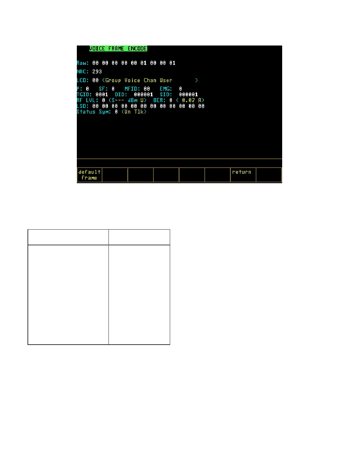
Figure 21-14. Voice Frame Encode - Generate
The embedded information associated with a
particular Link Control Opcode Identifier is
available for encoding from the user interface:
Mnemonic
Default Value
Link Control Opcode (LCO) 0
Priority (P) 0
Standard Format (SF) 0
Manufacture ID (MFID) 0
Emergency Bit (EMG) 0
Talkgroup ID 1
Destination ID (DID) 1
Source ID (SID) 1
RF Lvl 0
Bit Error Rate(BER) 0
The user interface provides entry of the
embedded signaling information as hexadecimal
numbers. A softkey that sets the encoded
embedded signaling information to a default
frame is provided. Default values are shown in
the table above.
Selection of the default embedded signaling
values causes an information message to verify
the network ID to be displayed.
21-9.3 1011 Hz Tone Test Pattern
The Audio Zone provides for selection of a 1011
Hz Tone Test pattern. In generate mode, control
is provided for setting the frequency deviation of
the 1011 Hz Tone Test Pattern baseband signal
that is used to modulate the Project 25 RF
transmissions.
21-9.3.1 Monitor Mode
When MONITOR is selected in the RF Zone and
the 1011 Hz Tone Test pattern is selected for the
Audio Zone “Code:” field, the analyzer is
configured to receive a 1011 Hz Tone Test
pattern. The received 1011 Hz Tone Test pattern
will be compared with a stored version of the
pattern and a BER will be computed. The
computed BER can be displayed in the Display
Zone when BER is selected for the “Meter:” field
in the Display Zone.
NOTE
The Monitor mode must be selected to compute
BER.
272
 Loading...