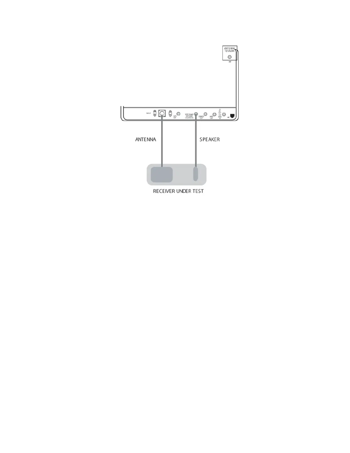
Figure 14-5. Basic FM Receiver Testing Setup
14.6 VOICE PATTERN TESTING IN
MONITOR MODE
This section contains basic test setup for FM
transmitters. Testing procedures are contained in
Section 4 of the General Operations tab of this
manual.
CAUTION
For transmit power output measurements,
connect the transmitter under test only to
the analyzer's RF I/O port. Do not connect
it to the ANT port. The ANT Port is used
with an antenna for over-the air testing.
The built-in RF load dissipates up to 50 W
for three minutes and up to 125 W for one
minute. If a high-power transmitter is keyed
into the analyzer long enough to threaten
overheating the power measuring circuitry,
the analyzer's audible alarm sounds and the
display changes to the
RF LOAD
OVERTEMPERATURE
warning, signaling
the operator to unkey.
Refer to Figure 14-6. Connect the analyzer's RF
I/O port to the RF output of the transmitter under
test. Connect the analyzer's MOD OUT jack to
the mic audio input of the transmitter under test.
198
 Loading...