NOTE
For setup and distortion measurements, set
output level to at least 30 dB above sensitivity
threshold (-80 dBm recommended).
3. Connect the analyzer’s RF I/O port to the
radio’s antenna connector.
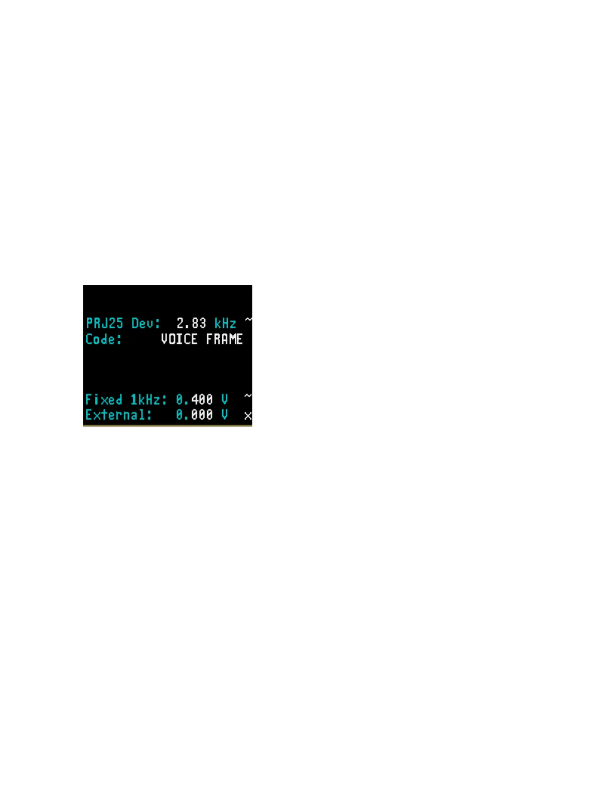
4. Use the CURSOR ZONE keys to move the
cursor to the Audio Zone. Within the Audio
Zone, move the cursor to “Fixed 1 kHz:”
field. Select 1 kHz audio source as the
modulating signal (also available from the
MOD OUT connector on the front panel) by
turning 1 kHz on “~”. Set 1 kHz voltage level
to 0.4 volt.
5. Turn on the PROJ 25 CONV receiver and
tune receiver and analyzer to the same
frequency. Verify receiver locks onto test
signal.
6. Use the CURSOR ZONE keys on analyzer
front panel and move the cursor to the
Display Zone.
7. Place cursor in the “Display:” field and press
CLEAR SCOPE screen should appear
similar to Figure 22-4.
8. Move the cursor to “Horiz:” field and press
200 us softkey.
9. Move the cursor to “Vert:” field and press
200 mv softkey.
10. Move the cursor to “Vert Position:” field.
Use move up/move down softkeys or rotary
control to position the modulating 1 kHz
waveform on a convenient graticule.
11. Move the cursor to “Horiz Position:” field.
Use move left/move right softkeys or rotary
control to position the modulating 1 kHz
waveform on a convenient graticule.
12. Move the cursor to “Mrk:” field.
Press V softkey to display movable
markers that measure voltage
differential (Vp-p).
Press T softkey to display movable
markers that measure time differential
(sec).
Press 1/T softkey to display movable
markers that measure reciprocal time.
13. Position the markers as desired using TUNING
knob (press toggle marker softkey to select
marker). The movable marker is indicated by a
red line. Observe digital readout of marked
values below “Mrk:” field.
288
 Loading...