Chapter 3: ProView 2900 Control Interfaces Installation Instructions
© Harmonic Inc. Manual p/n 101543/Ver 1.0 3-4 ProView 2900 Series/SW Version 1.94
• Bei Anbringung dieser Einheit in einem zum Teil gefüllten Gestell ist das Gestell von
unten nach oben zu laden, wobei das schwerste Bauteil unten im Gestell anzubringen ist.
• Wird das Gestell mit Stabilisierungszubehör geliefert, sind zuerst die Stabilisatoren zu
installieren, bevor sie die Einheit im Gestell anbringen oder sie warten.
To mount the 19”/42U rack with the ProView 2900 units perform the following:
1. Verify using of appropriate brackets and L” shape slides according to 3.2.2.1 and
3.2.2.2.sections.
2. Mount the ProView 2900 in groups of five units (maximum) upon each pair
of brackets.
3. Leave ‘one-unit-space’ between each group of five units.
NOTE: The maximum number of ProView 2900s per a 19”/42U rack is 35 (seven
groups of five units).
CAUTION: Ensure that a sufficient amount of airflow enters the ProView 2900
from the left end (from the front panel point of view)
Consider if other devices in the rack use airflow in the opposite direction.
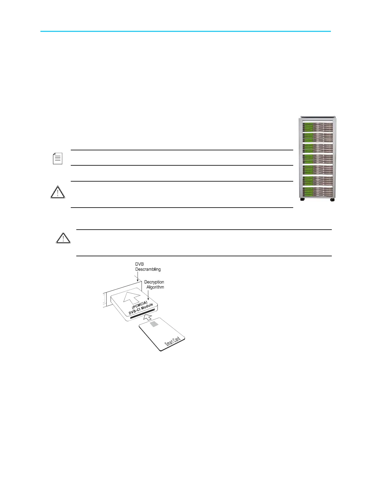
3.2.3. Insertion of the DVB-CI Module (PCMCIA)
Caution
Do not remove or insert the DVB-CI module or the Smart Card while the ProView 2900 is
powering up or initializing.
Figure 3-1: DVB-CI Module
Figure 3-1 illustrates the ProView 2900 with the
DVB-CI module (PCMCIA card) and the Smart
Card used to decrypt the incoming signal. The
ProView 2900 is provided with two PCMCIA slots
for up to two DVB-CI modules. The PCMCIA
should be firmly inserted into one of the two
provided slots to ensure contact. Each DVB-CI
module accommodates one Smart Card, inserted
with the UP mark pointing upwards and forward.
When installed, the card is detected automatically
by the ProView 2900 and enabled if the three
following conditions are valid:
• The installed card must be EN50221 compatible
• Services have been selected at TV1/TV2 (for further
information see section 8.2)
• Using a valid card licensing