Wireless LAN – WLAN
110
3.7
IEEE 802.11i for point-to-point connections
BAT54-Rail/F..
Release
7.54
06/08
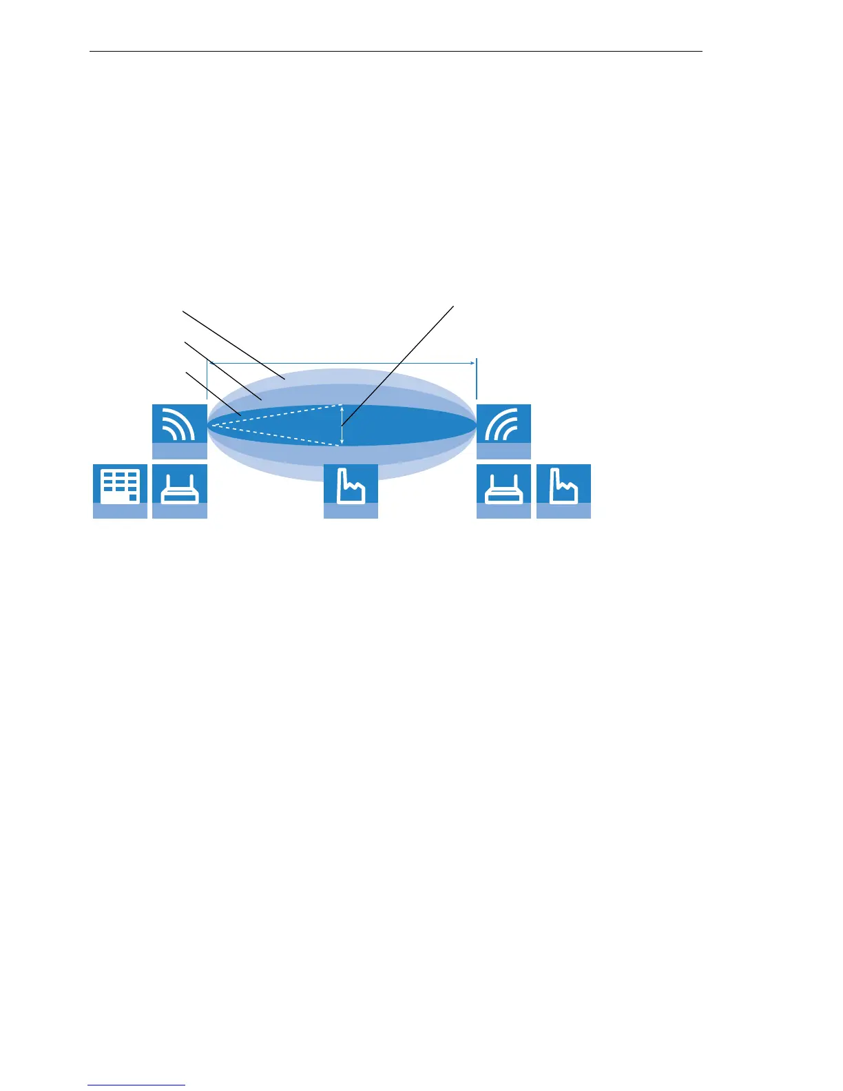
U Positioning the antennas
Antennas do not broadcast their signals linearly, but within an angle that de-
pends on the model in question. The spherical expansion of the signal waves
results in amplification of or interference to the effective power output at cer-
tain intervals of the connection between the transmitter and receiver. The ar-
eas where the waves amplify or cancel themselves out are known as Fresnel
zones.
The Fresnel zone 1 must remain free from obstruction in order to ensure that
the maximum level of output from the transmitting antenna reaches the re-
ceiving antenna. Any obstructing element protruding into this zone will sig-
nificantly impair the effective signal power. The object not only screens off a
portion of the Fresnel zone, but the resulting reflections also lead to a signif-
icant reduction in signal reception.
The radius (R) of Fresnel zone 1 is calculated with the following formula as-
suming that the signal wavelength (
λ) and the distance between transmitter
and receiver (d) are known.
R = 0.5 *
√ (λ * d)
The wavelength in the 2.4 GHz band is approx. 0.125 m, in the 5 GHz band
approx. 0.05 m.
Example: With a separating distance of 4 km between the two antennae, the
radius of Fresnel zone 1 in the 2.4-GHz band is 11 m, in the 5-GHz band 7 m.
To ensure that the Fresnel zone 1 remains unobstructed, the height of the an-
tennas must exceed that of the highest obstruction by this radius. The full
height of the antenna mast (M) should be as depicted:
WLAN Router
ANTENNA
ADMINISTRATION
ACCESS POINT
ANTENNA
PRODUCTIONOBSTRUCTION
Fresnel zone 1
Fresnel zone 2
Fresnel zone 3
Radius R
Distance d