Using Instrument Functions
Using Markers
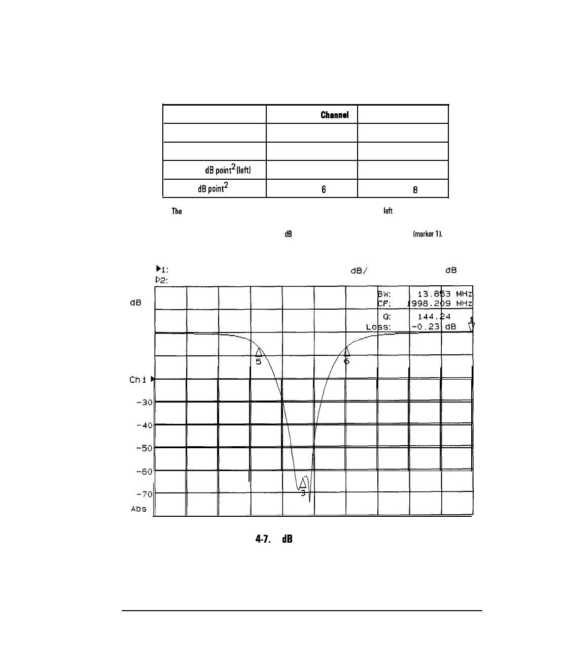
Dedicated Use of Markers in Notch Search Mode
Dedicated Use
Measurement
Chennel
1 Measurement Channel 2
maximum power value
marker 1
marker 2
center frequency of stop band’
marker 3
marker 4
notch -n
dB
point’
lleftl
marker 5
marker 7
notch -n
dB
point2
lrightl
marker 6
marker 8
1
The
center frequency is defined by the analyzer as the midpoint between the left and right notch
points.
2 Where n is the target value, and the -n
dB
point is relative to the maximum response
(marker
II.
)I:
Transmission
Log Mag 10.0
dB/
Ref -20.00
dB
C
D2:
off
;;;
10
0
1
-10
Chl
Center 2 000.000 MHz
Span 50.000 MHz
Figure 4.7. -6
dB
Notch Marker Search
4-16