Making Measurements
Using the BEGIN Kay to Make Measurements
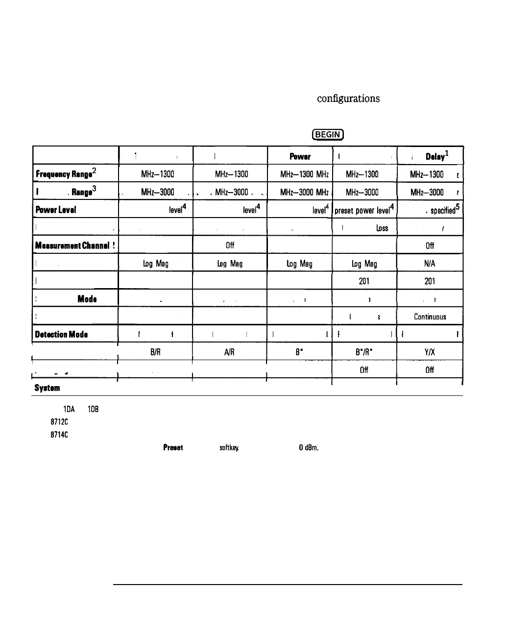
Depending on your selection, the analyzer is set to one of the following
configurations. (The SRL and Fault Location
confIgurations
are discussed in
the Option 100 User’s Guide Supplement.)
Table 3-1. Measurement Configurations from the
@iZiQ
Kay
Conversion Loss
AM Delay’
Transmission
Reflection
Power
1
10
MHz-1300
MHz
Frequrncy
Rango 0.300
MHz-1300
MHz 0.300
MHz-1300
MHz 10
MHz-1300
MHj
Frequency
Rango’
0.300
MHz-3000
MHz 0.300
MHz-3000
MHz 10
MHz-3000
MHI
10
MHz-1300
MHz
10
MHz-3000
MHz 10
MHz-3000
MHz
oreset
Dower
level4 maximum
soeciiied5
Powor
Levrl
preset power
level4
preset power
level4
preset power level4
Measurement Channel 1
Transmission
Reflection Power Conversion
loss
AM Delay
Maasurmaont
Channel
2
Format
off
Log
Mag
Off
log
Mag
off
h
Mag
N/A
Number of Points
Swoop Time Mode
201 201
201
Auto Auto Auto Auto Auto
Continuous
Sweep Triggering
Dotaction
Mode
Continuous
Narrowbend
Continuous
Narrowbend
Continuous
Broadband Internal
Broadband Internal Broadband External
I
Measurement Paths
I
B/R
I
I
Avoraaina
I
Off
I
Off
I
Off
I
System Bandwidth
I
Medium Wide
I
Medium Wide
I
Medium Wide Medium Wide Narrow
1 Options
1OA
and
10B
only
2 HP
871X
3 HP
8714C
4 Preset power level is user-defined by using the
Prmt
Pwr Level
softkqc
The factory default is 0
darn.
5 Maximum power is dependent upon the option configuration of your analyzer. See Chapter 10 to determine the maximum specified power for your analyzer.
3-16