I
-
I
-
Making Measurements
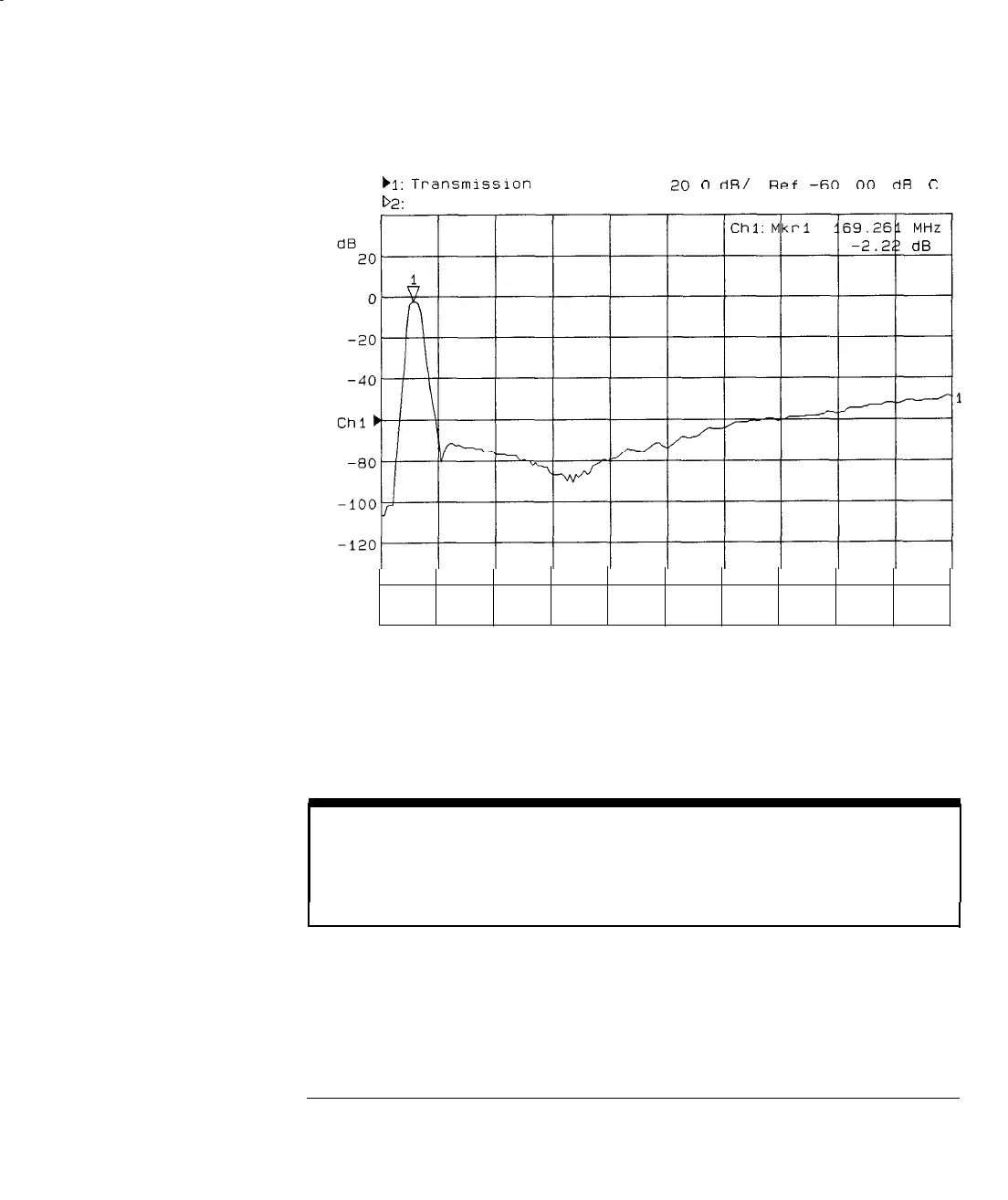
Measuring Transmission Response
)I:
Transmlsslon
D2:
Off
Log Mag
2n
n
dR/
RPf
-60
00
rlfl
c
-140
Abs
Start 0.300 MHz
Stop 3 000.000 MHz
Figure 3-6. Example of a Transmission Measurement Display
5. See “Using Markers” in Chapter 4 for more detailed information on using
markers to interpret measurements.
NOTE
For the measurement to be valid, input signals must fall within the dynamic range of the analyzer. See
Chapter 5 for techniques to increase the dynamic range of the analyzer.
3-23
-1
I-