User’s Manual INNOMAR Parametric Sub-Bottom Profilers / SESWIN 17
Innomar Technologie GmbH (2023-01) 17
2 Quick Start Guide
2.1 Transducer Handling & Installation
See section 3.2 on page 26 for details on transducer handling and installation.
!
Make sure the transducer fits to the topside model used (letter in s/n, see page 26).
Check transducer visually (face, cable, connector) do not use damaged equipment,
there are high voltages used inside, which may be lethal!
The transducer must not be operated in air
Guidelines:
Protect the transducer face (mechanical impact, chemicals, direct sunlight).
Protect the cable (mechanical impact), avoid vibrations and strong bending preferably
route within pole.
Protect the connector, it is NOT water-proof.
For long-term deployments use zinc anodes and anti-fouling.
The transducer face has to be horizontal, the arrow pointing forward (to bow).
(there are no arrows on the “smart” and “quattro”/“sixpack” transducers)
Avoid vibrations; use rubber washers as provided and support the mounting pole.
Place transducer as far as possible from noise sources near vessel’s bow.
Avoid air bubbles washed beneath the transducer.
Use extra ground wire from transducer to topside unit to reduce electrical noise.
During operation the transducer has to be covered by water at all times.
Connect / Disconnect to topside unit only if power is switched off.
After demobbing clean with fresh water and dry before storage.
2.2 Topside Handling & Installation
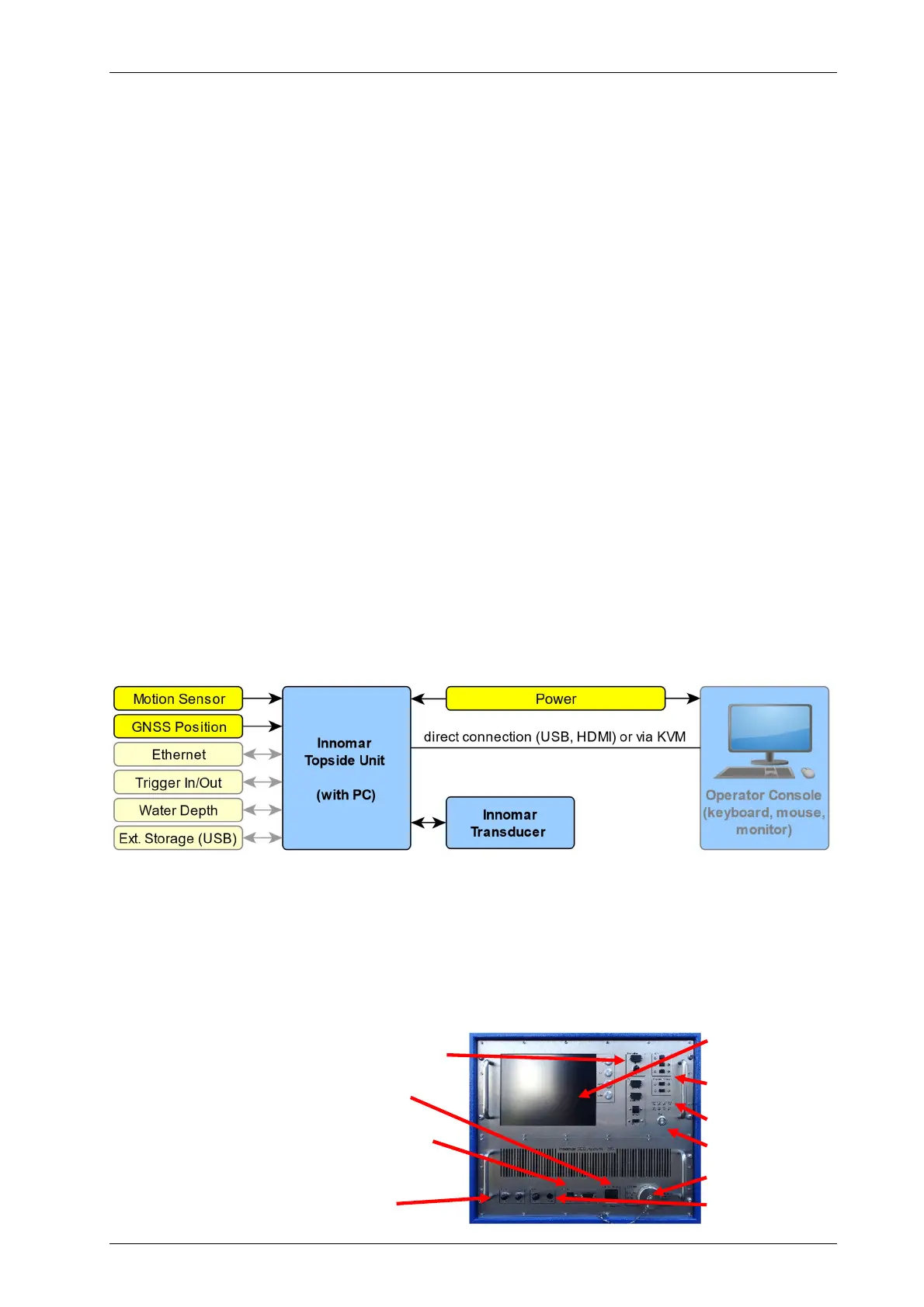
INNOMAR SBP general components (actuals depending on SBP model)
See section 3.3 on page 32 for details on topside unit handling and installation.
!
Check topside visually (connectors, cables, housing) do not use damaged
equipment, there are high voltages used inside, which may be lethal!
Handle topside with care, keep clean, dry and secured; protect against water.
Ensure proper airflow to avoid hot spots.
Secure all components and connections.
GNSS position input (NAV-IN; Ethernet or
serial port; update rate preferably 10Hz)
Power (for most models mains
100–240 V, 50–60 Hz AC)
Motion sensor input (Ethernet or serial
COM port; update rate preferably 50Hz)
Trigger / external synchronisation to
reduce acoustic interference
TFT display +
controls
PC interfaces
Status LEDs
Power switch
Transducer
GND