User’s Manual INNOMAR Parametric Sub-Bottom Profilers / SESWIN 53
Innomar Technologie GmbH (2023-01) 53
5.9.6 Home – Transmit SBP (not for “smart” model)
Here you set the centre frequency and pulse length of the SBP LF channel. Frequency and pulse
length chosen during data acquisition are final, they affect the recorded data directly!
The HF frequency is fixed, see table below. The HF pulse length (in time) is the same as set in
this menu for the LF pulse length.
SBP model smart compact, light-xx,
standard-xx,
medium-100, medium-usv
medium-70 deep-36 deep-15
Mean HF (kHz) 100 100 70 36 15
LF range (kHz) 10 4 – 15 3 – 12 2 – 7 1 – 4
The LF Frequency has to be chosen depending on the survey task. Lower frequencies will
achieve better penetration than higher frequencies, but at reduced resolution. Higher frequencies
will achieve better resolution, but with reduced penetration. Usually, higher frequencies are used
due to better efficiency and better signal to noise ratio and better resolution.
A good starting point for usual survey work is the centre of the given frequency range
(10 kHz for the shallow-water models).
LF-Pulses represent the number of cycles of the LF centre frequency that are transmitted. The
energy of the transmitted signal is increased if the number of pulses is increased. That improves
the signal-to-noise ratio but decreases the resolution. The available range depends on the
chosen frequency. The number of pulses should be as small as possible, if the detection of small
reflectors or the resolution near the sediment surface are of high priority, but the higher bandwidth
will be more prone to noise. A good starting point is in the middle of the given range.
The actual pulse width PW in milliseconds can be calculated from the number of LF pulses N and
the frequency F in kHz: PW = N/F. Example: 10 kHz at 2 pulses results in 2/10 = 0.2 ms.
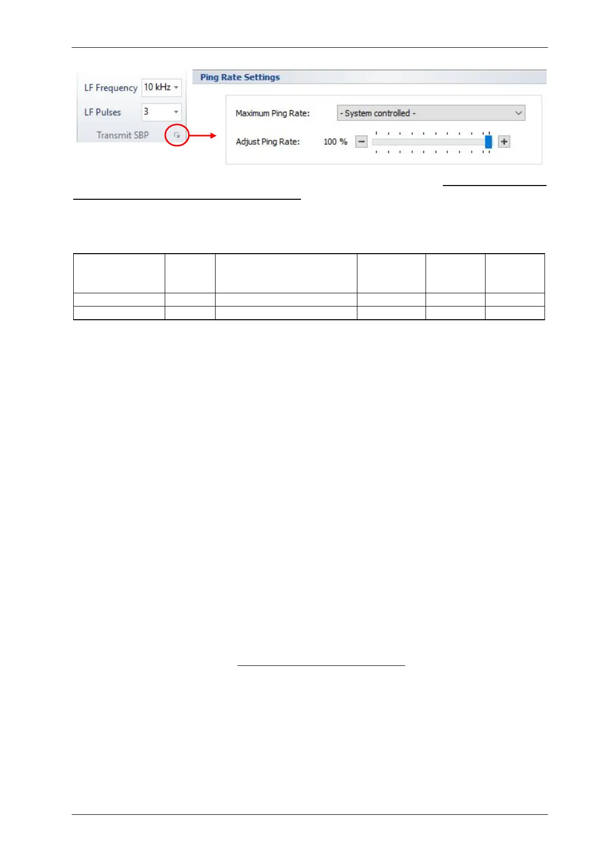
Ping Rate Settings
If required, the Maximum Ping Rate can be set manually. The default “System Controlled”
ensures the ping rate as high as possible. The “system” ping rate can be estimated as follows.
Between subsequent pings there is a dead time of approx. 10 ms. Supposing a sound velocity of
1500m/s, the resulting ping rate in “normal” ping mode (internal trigger) is:
≈
750
+ ℎ + 7.5
In shallow water with short range settings the ping rate might be reduced to ensure the resulting
duty cycle (pulse length relative to ping interval time) is not higher than the allowed maximum
value of 1.4 percent.
Adjust Ping Rate: Using this slider one can reduce the ping rate. This may be useful in case of
high reverberation or to check for multiples.