70 User’s Manual INNOMAR Parametric Sub-Bottom Profilers / SESWIN
70 Innomar Technologie GmbH (2023-01)
Offset Correction for Transducer
For the transducer an individual offset for the X, Y and Z value can be selected. The offset values
are unit-free but should refer to the same coordinate system as the incoming “SIS data” defined
in “Position and Heading Data Source” above (meters for UTM coordinates).
The offset values are pointing from GNSS antenna to transducer position, the GNSS antenna is
supposed to be at the origin (0, 0); the x-axis points starboard and y-axis points forward.
Make sure to select the same coordinate system for the SIS and the offset values!
Coordinate Processing
The only option is to enable or disable the transducer offset correction. The correction is
calculated online every time new position and heading values are received.
Take care! The system will use the heading information as specified by 'Heading Data Source'.
If that data is incorrect (or does not exist), either incorrect position data will be stored or an error
window will show up!
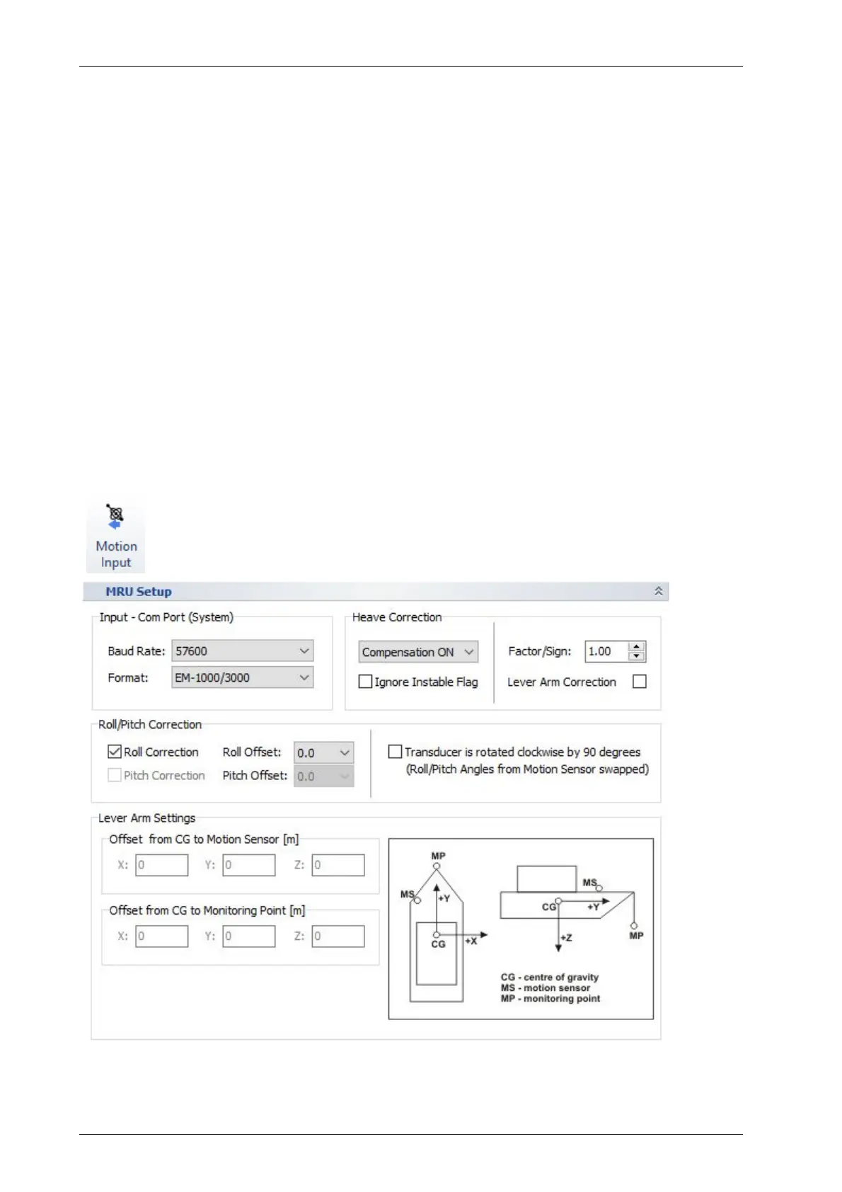
5.11.14 System Setup – Settings – Motion Input
Defines the data format as well as the COM port baud rate of the motion sensor
used. The port itself is defined in the SESWIN start splash screen.
Some heave processing including lever arm correction can be set up.
For this Dialog see also section 7.5 on page 98.
For naming conventions and directions refer to the picture below.