88 User’s Manual INNOMAR Parametric Sub-Bottom Profilers / SESWIN
88 Innomar Technologie GmbH (2023-01)
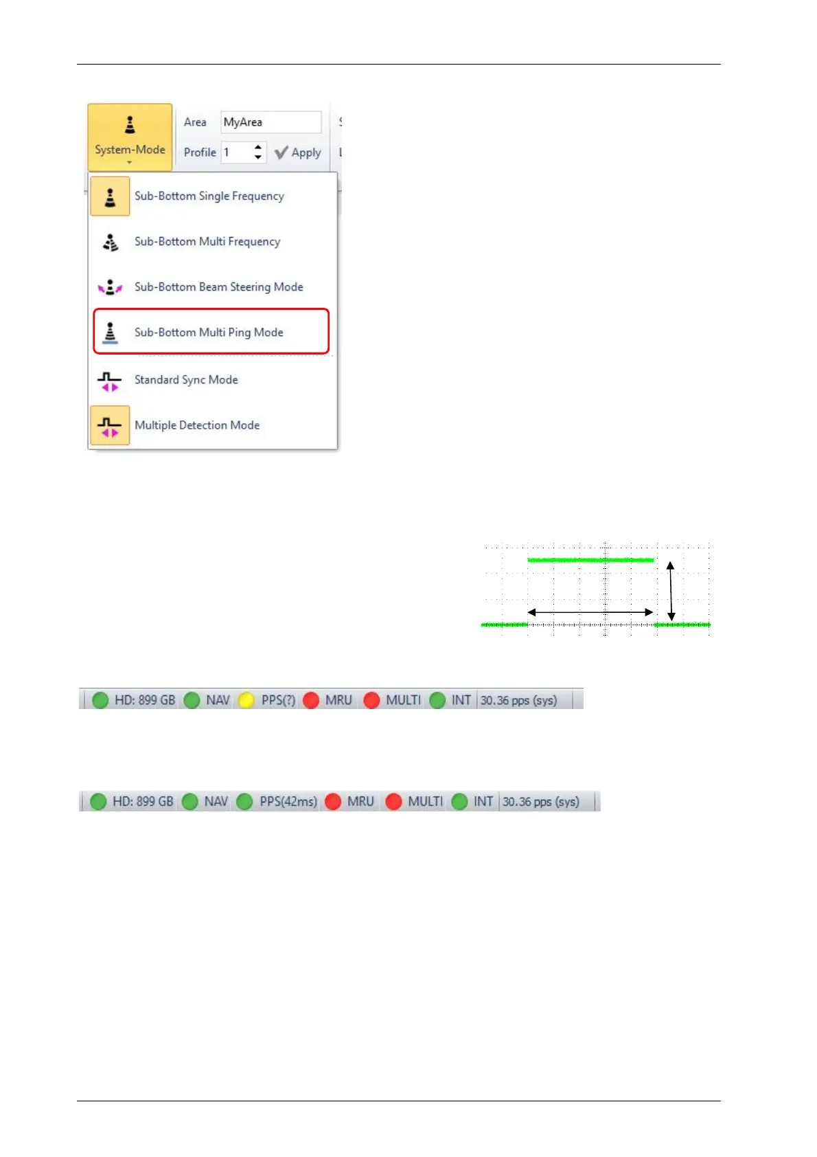
6.4 Sub-Bottom Multi-Ping Mode (not for “smart”)
For most models there is a special “Multi-Ping Mode”
available to ensure the highest possible ping rate even
in deep waters. This will produce equidistant pings.
This mode is activated in the SESWIN “Home Menu –
General – System Mode”, see picture.
The “Multi-Ping Mode” is possible with internal trigger
only.
In “Multi-Ping Mode” additional pings are placed
between the “normal” pings, if possible. For this the
“Range Start” has to be at least 40 m and larger than
3 times “Range Length”.
If the “Multi-Ping Mode” is used, there may be artefacts
visible in the data that are produced by water-column
features (e.g., fish schools) or additional multiple
echoes. To check if features visible are real, you
should switch off deep-sea pulse mode temporarily.
It is also important to ensure the water depth is correct
and the data collected are nut just from a multiple
reflection.
6.5 1-PPS Input
The “1-PPS” pulse is expected at pin 1 of the “Nav IN”
connector (serial DB9). On some systems is an
additional dedicated BNC socket.
The “1-PPS” pulse needs to be TTL (5V positive) level,
pulse width ideally 1ms duration.
If such pulse is detected by SESWIN the “PPS” indicator in SESWIN’s status bar turns yellow,
independent on position data available at “Nav IN”.
If a “$xxZDA” message is received within the “NavIn” data and the PC time sync set to “$xxZDA”,
the “PPS” indicator turns green and the delay between the “1-PPS” pulse and the next “ZDA”
message is shown:
This “1PPS” delay value can be used for quality assurance. Anyhow, there is no correction for
the position data applied based on the “1-PPS” pulse within SESWIN. The delay is not stored
within the INNOMAR SES and RAW data formats, but with the SES3 data format.
!
There is no connection (neither physical nor logical) between the “Sync IN” trigger input
and the “1-PPS” signal.
On older systems the “1PPS” was connected to pin 9 of the “Nav IN” socket.
!
The “1PPS” input works only if the position data is fed to the Innomar via the serial RS232
“Nav IN” socket, it is not working if the position data is sent via Ethernet/UDP.
1ms
5V