180 User’s Manual INNOMAR Parametric Sub-Bottom Profilers / SESWIN
180 Innomar Technologie GmbH (2023-01)
Transducer Cable
Two BURTON connectors (6611-3239 and 5511-3239) wired one to one, cable with 19 twisted
pairs and common screen.
Pins 1-2 ... 11-12 Twisted pairs (transmitters 1 ... 6)
Pins 13-14 “Transducer Plugged” safety circuit
Pins 15-16 ... 17-18 Twisted pairs (transmitters 7 ... 8)
Pins 19-20 GND
Pins 21-22 ... 35-36 Twisted pairs (transmitters 9 ... 16)
Pins 37-38 not used
Pin 39 Cable screen
Dust Caps and Dummy Plugs for Connectors and Cables
Qty Dummy Plug Dust Cap (hard rubber)
transducer connector at subsea unit 1 6601-3239-0000 A 6700-0520-0000
transducer connector at transducer 1 5501-3239-0000 A 6700-0124-0321
interface connector at subsea unit 1 5501-2013-0000 A 6700-0124-0201
interface cable connector 1 6700-0125-0201
transducer cable connectors 2 6700-0125-0321
The use of dust caps will keep the connectors clean and help prevent accidental damage both
during storage and service. Anyhow, these caps are not water proof! Therefore, dummy plugs
should be used on all unused connectors if the system is mounted on the ROV.
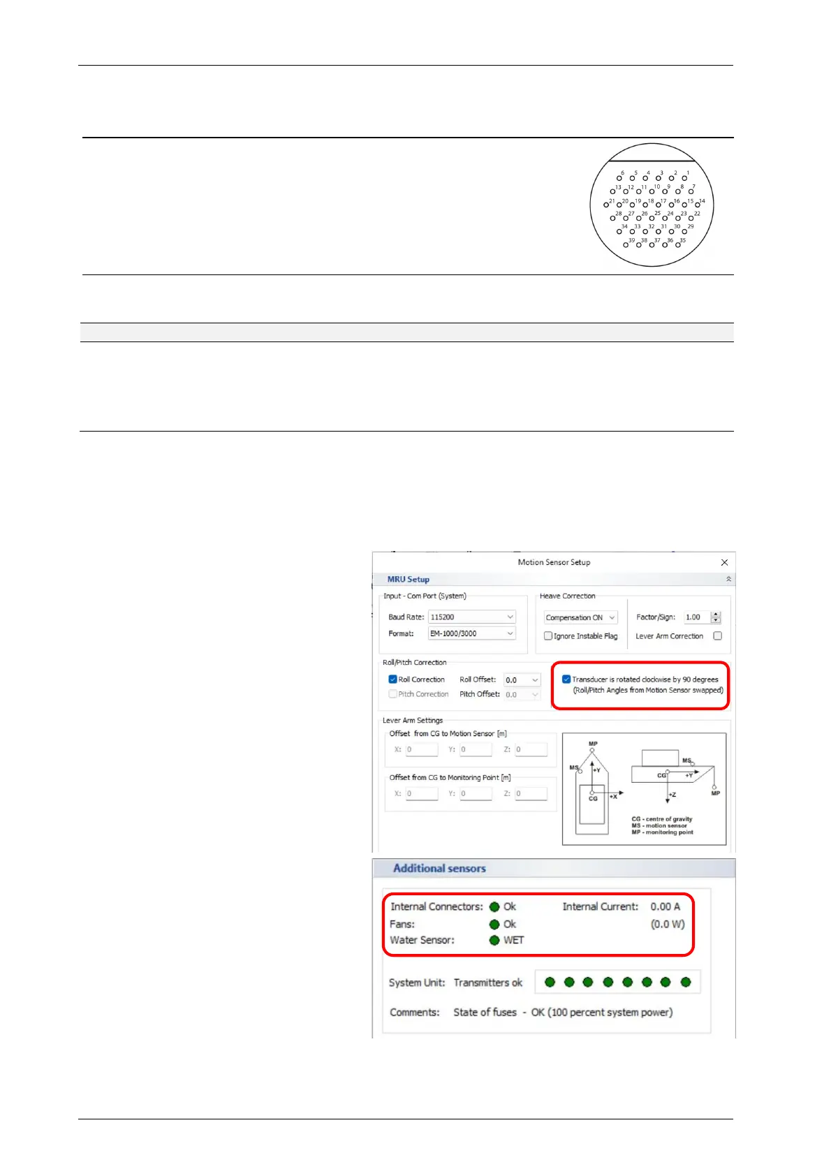
Special “standard-rov” SESWIN Settings
On ROVs usually the main transducer tilt
is in Pitch and not in Roll direction.
Therefore, the default transducer moun-
ting as shown on the previous page, is for
pitch compensation. For this mounting
the “transducer is rotated” check box has
to activated in the SESWIN “Motion
Sensor Setup”.
There are some additional sensors, those
status is shown in the “System Status”:
Internal connectors plugged
Fans working
“System in Water” sensor status
Power consumption