30 User’s Manual INNOMAR Parametric Sub-Bottom Profilers / SESWIN
30 Innomar Technologie GmbH (2023-01)
like the INNOMAR systems. A small positive inclination (bow up, max. 0.5°) is acceptable in order
to ensure laminar water flow. Avoid negative inclination since this may cause turbulences.
Electrical connection / grounding: To reduce noise caused by the mains generator the
transducer’s housing should be electrically connected to the topside unit by an additional ground
wire.
Prevent bio-fouling: To reduce bio-fouling, hull-mounted transducers have to be painted with an
approved water-based anti-fouling compound, see below.
Prevent corrosion: If the transducer is situated in water for a longer period of time, use zinc
anodes to prevent corrosion. Proper grounding is also essential.
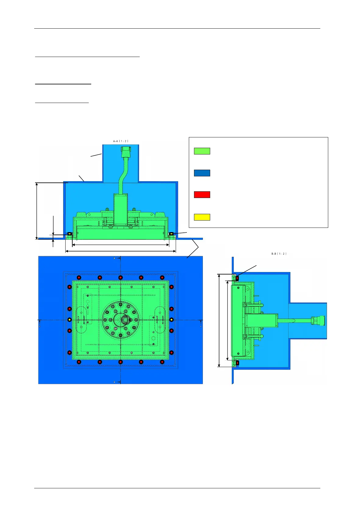
Sea Chest / Gondola Preparation
Sketch showing the INNOMAR “medium-100” hull-mount transducer with mounting frame as delivered by Innomar
(green parts) and all parts to be prepared by the ship yard: sea chest with mounting flange and stand pipe (blue),
threaded holes M10 (red) and water inlet holes (yellow) in the mounting flange.
To affix the transducer there are threaded holes (or drilled holes with hex nuts welded on top) in
the flange (marked red in the sketch above). There are also two water inlets (marked yellow) in
the flange to ensure the sea chest is flooded. Innomar provides a drilling template for all
holes/threads in the flange. The holes should be drilled after welding the flange. The drilling
template can also be used to verify if the transducer fits into the rectangular cut-outs.
Legend
Transducer with mounting frame
and cable (provided by Innomar)
Sea chest, stand pipe, flange
(ship yard)
Threaded mounting holes M10 in flange
(ship yard)
Water inlet holes in flange (ship yard)
stand pipe
sea chest
mounting flange
vessel hull
mounting flange