3-22 Basic DMM Operation Model 2700 Multimeter/Switch System User’s Manual
Model 7700 switching module
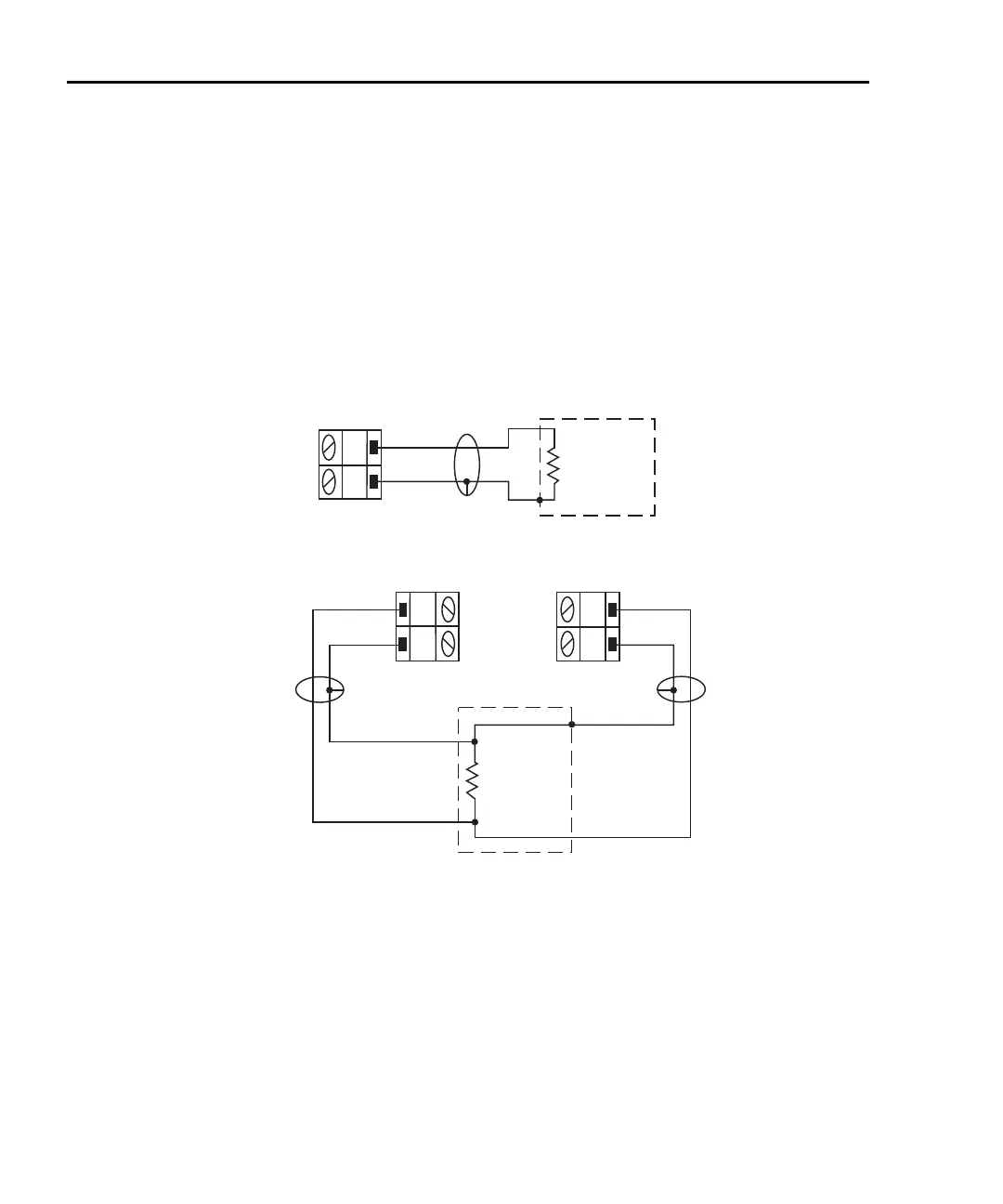
Connections for the switching module are shown in Figure 3-9. As shown in Figure 3-9A,
each of the 20 channels can be used to perform Ω2 measurements. For Ω4 measurements, a
channel pair is used for each 4-wire measurement as shown in
Figure 3-9B.
For Ω4 connections, channels 1 through 10 (which are used as the INPUT terminals) are
paired to channels 11 through 20 (which are used as the SENSE terminals). Channel 1 is
paired to channel 11, channel 2 is paired to channel 12, and so on.
Figure 3-9
Ω2 and Ω4 connections for Model 7700 switching module
Shielding
To achieve a stable reading, it helps to shield resistances greater than 100kΩ. As shown in
Figure 3-8 and Figure 3-9, place the resistance in a shielded enclosure and connect the
shield to the input low terminal of the instrument electrically.
H
L
CH 1-10
Model 7700
Switching
Module
H
L
CH 11-20
B. Ω4 Connections
INPUT
SENSE
Resistance
Under Test
Optional Shield
Shielded
Cable
Shielded
Cable
H
L
CH 1-20
Model 7700
Switching
Module
Resistance
Under Test
Shielded
Cable
Optional Shield
A. Ω2 Connections
Note: Source current flows from input
high (H) to input low (L).

 Loading...


