4-18 Range, Digits, Rate, Bandwidth, and Filter Model 2700 Multimeter/Switch System User’s Manual
Filter control and configuration
The FILTER key toggles the state of the Filter. When the Filter is enabled, the FILT
annunciator is on. The FILT annunciator will flash when the filter is not settled. When
disabled, the FILT annunciator is off. The filter can be configured while it is enabled or
disabled.
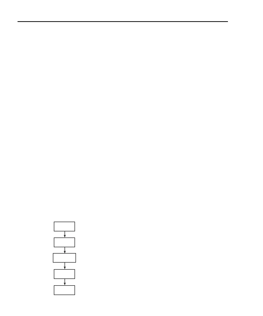
The filter is configured from the filter configuration menu (Figure 4-4). Perform the
following steps to configure the filter:
1. Select the desired function.
2. Press SHIFT and then TYPE. The present WINDOW setting will be displayed.
3. Use the RANGE Δ or ∇ key to display the desired window setting (0.01%, 0.1%,
1%, 10%, or NONE), and press ENTER.
4. Use the , , Δ, and ∇ keys to display the number of readings to filter (1 to
100), and press ENTER.
5. Use the Δ or ∇ key to display the desired filter type (moving or repeating), and
press ENTER. The filter turns on and the instrument returns to the normal
measurement state.
NOTE While the filter is enabled (FILT annunciator on), changes to the configuration
take effect as soon as they are made. With filter disabled (FILT annunciator off),
changes to the configuration take place when the filter is enabled.
While the filtering operation is in progress, the FILT annunciator blinks.
Readings will continue to be processed (i.e., displayed, stored, sent over the
bus), but they could be questionable. When the FILT annunciator stops blinking,
the filter has settled.
Changing function or range causes the filter to reset. The filter then assumes the
state (enabled or disabled) and configuration for that function or range.
Figure 4-4
Filter configuration flow chart
SHIFT
TYPE
WINDOW
0.01%
0.1%
1%
NONE
RDGS
001 to 100
TYPE
REPEAT
MOVNG AV

 Loading...


