1-30 Getting Started Model 2700 Multimeter/Switch System User’s Manual
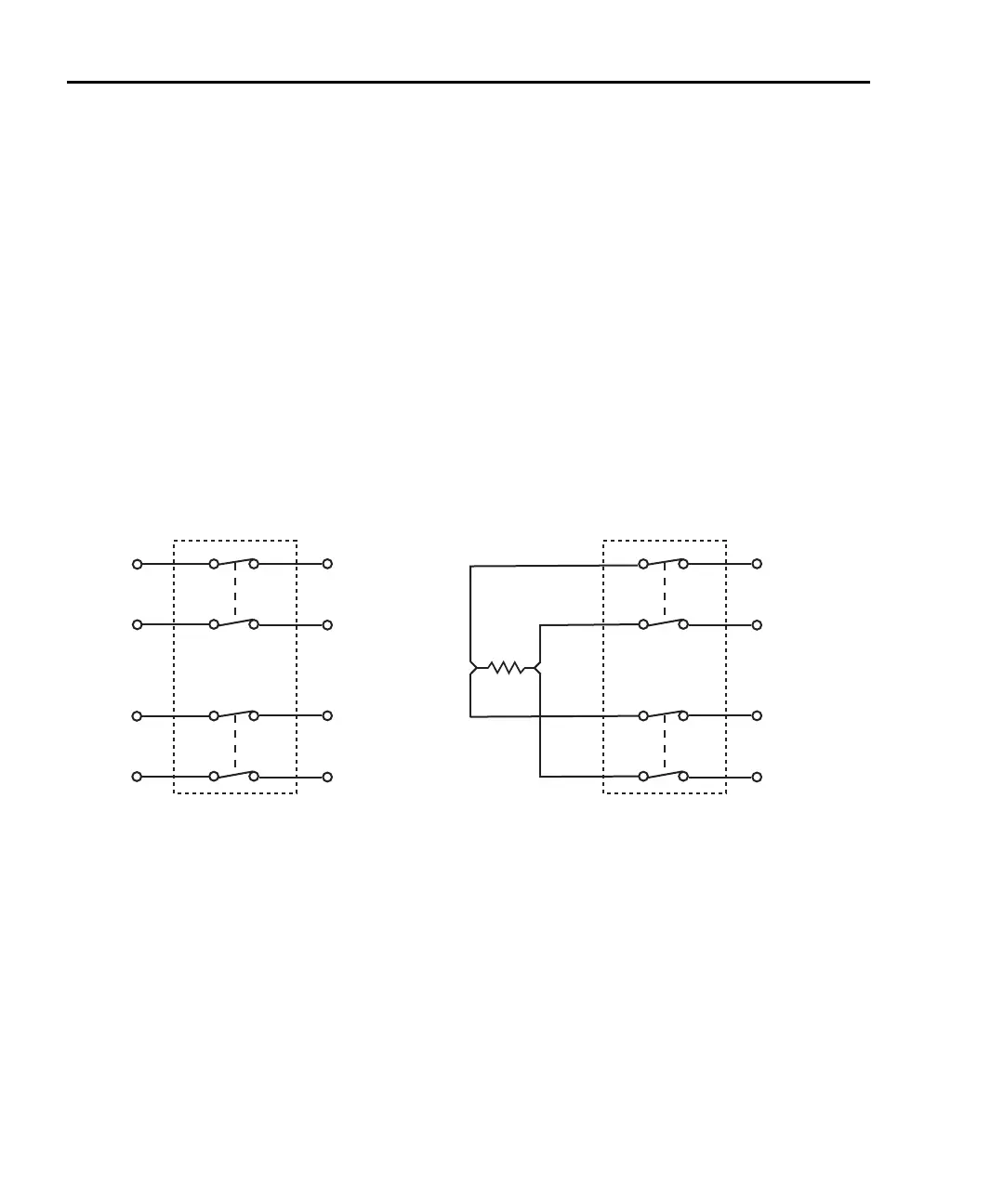
• For a 4-wire function (i.e., Ω4), a channel pair is connected to the DMM when a
system channel is closed. The system channel is connected to DMM Input and the
paired channel is connected to DMM Sense.
Figure 1-5 shows system channel 6 closed. For a 4-wire function, the paired
channel also closes. For the Model 7700, channels 1 through 10 are paired to
channels 11 through 20. When channel 6 is closed, channel 16 also closes.
Figure 1-5 shows how the DUT is connected to the DMM for the 4-wire function.
NOTE Figure 1-4 and Figure 1-5 show simplified schematics of the switching module.
They show a single switch closed to connect an input channel to the DMM. In
reality, multiple switching to is used to make proper connections to the DMM.
However, for system channel operation, the user need not be concerned about
which switches in the module close.
Figure 1-5
Connection to DMM for 4-wire function (system channel 106 closed)
NOTE Switching module channels can also be controlled using multiple channel
operation. This allows individual control of all module channels (switches).
Multiple channel operation should only be used by experienced service
personnel who recognize the dangers associated with multiple channel closures.
See
Section 2 for details.
Close/open operation
The following points on operation pertain to system channel operation only:
• Only one input channel (or channel pair) is closed at one time. When you close an
input channel, the previously closed input channel(s) will open.
DUT
DMM DMM
7700
Switching Module
7700
Switching Module
HI
LO
HI
LO
Input
Ch 6
HI
LO
HI
LO
Sense
Ch 16
HI
LO
Input
HI
LO
HI
LO
Sense
Ch 16
HI
LO
Ch 6

 Loading...


