268 Keysight N9010A EXA Service Guide
Analog/Digital IF Troubleshooting
25 MHz BW IF Section
Verifying the 22.5 MHz Output Power
1. Turn the instrument off.
2. Turn the instrument over so the bottom side of the analyzer is facing up.
3. Turn on the N9010A Signal Analyzer and wait for the instrument to
complete the boot up process.
4. Press System, Alignments, Auto Align, Off.
5. Press Input/Output, RF calibrator, 50 MHz.
6. Verify the 50 MHz signal is at −25 dBm by pressing FREQ, 50 MHz, SPAN,
1 MHz, Peak Search on the analyzer. The marker readout should be
50 MHz at −25 dBm ± 3 dBm. If this reference signal is measuring
incorrectly, see Chapter 4, “RF Section Troubleshooting (RF/Microwave
Analyzers)” in this service guide.
7. To continue verifying press SPAN, Zero Span. Verify the input attenuator
on the N9010A is set to 10 dB. Look near the top of the display near the
center and verify that Atten: 10 dB is visible. If needed change the input
attenuator by pressing AMPTD, Attenuation, 10 dB on the analyzer.
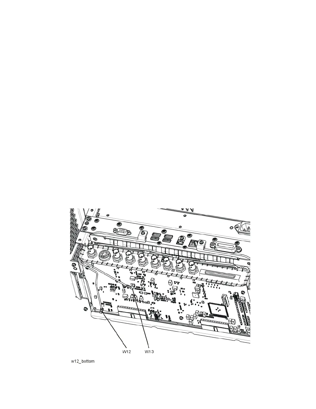
8. Refer to Figure 7-4, carefully disconnect the W13 cable at A3J15.
Figure 7-4 A3 Digital I.F. Cables

 Loading...


