Keysight N9010A EXA Service Guide 267
Analog/Digital IF Troubleshooting
25 MHz BW IF Section
9. Connect A13J7 to a functioning spectrum analyzer using the appropriate
SMA connectors and cables.
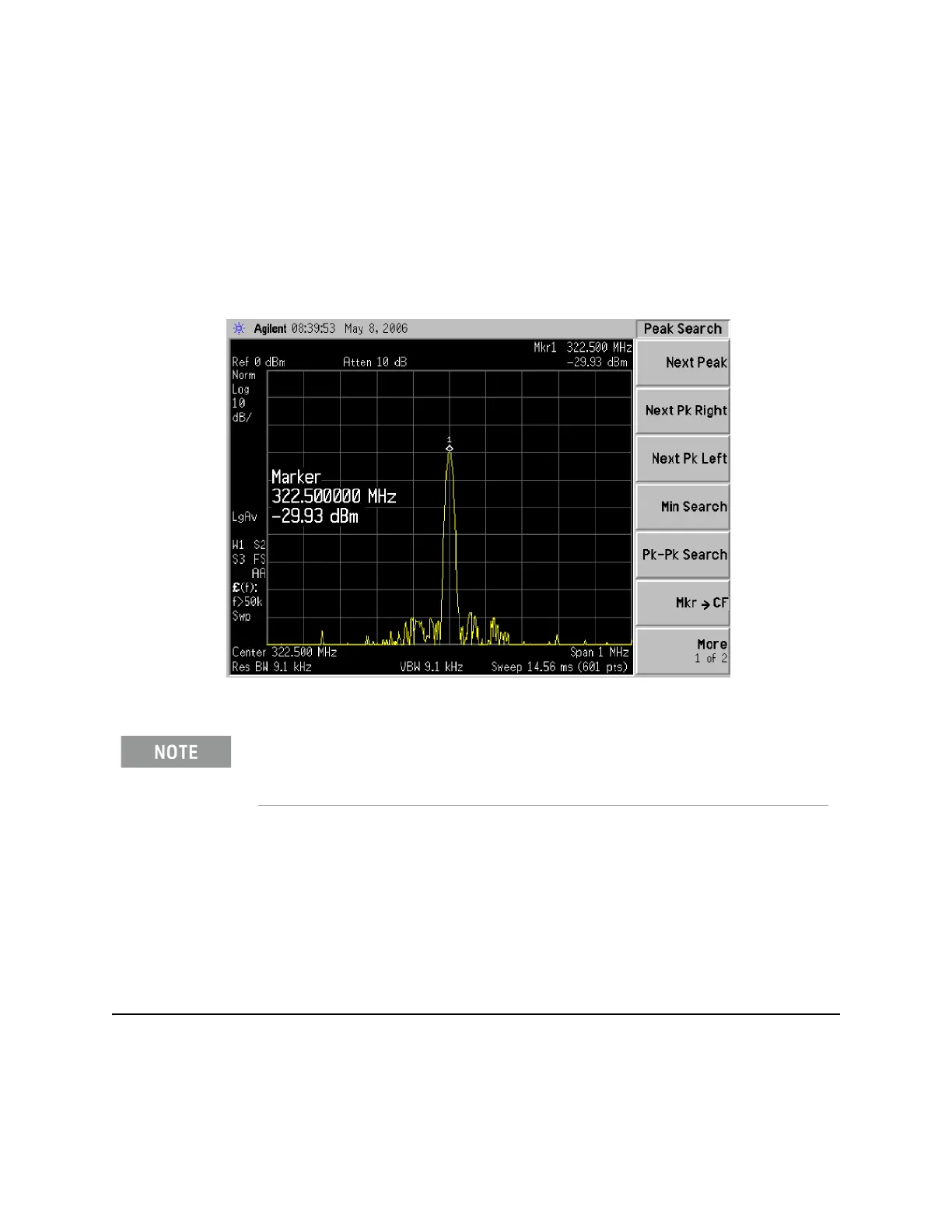
10.Press Freq, 322.5 MHz, Span, 1 MHz, Peak Search on the functioning
spectrum analyzer
11.The analyzer should read 322.5 MHz at −30 dBm ± 3 dBm as shown in
Figure 7-3.
Figure 7-3 A13 322.5 MHz Output
Reconnect W15 at A13J7.
IMPORTANT Measuring at this location is for convenience. The 322.5 MHz signal is an
output at A13J7. Since the W15 cable connects from this output to the input
of the Analog I.F. assembly at A2J100, the small coaxial cable has not been
tested at this point. If the analyzer is equipped with any combination of
options CR3, CRP, 532, or 544, the 322.5 MHz signal will also be routed from
A13J7 to A15J902 via W36 and from A15J900 to A2J100 via W37.
If the 322.5 MHz signal is not measuring the correct power level, refer to Chapter 4, “RF
Section Troubleshooting (RF/Microwave Analyzers).” in this service guide.

 Loading...


