286 Keysight N9010A EXA Service Guide
Analog/Digital IF Troubleshooting
40 MHz BW IF Section
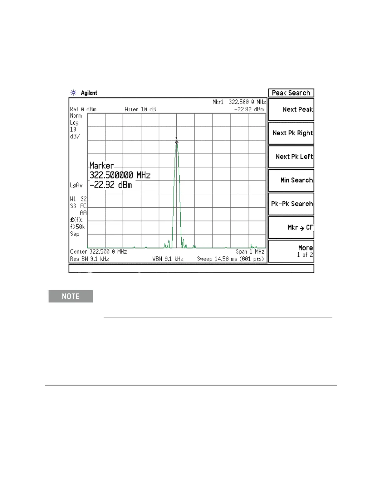
11.The analyzer should read 322.5 MHz at −23 dBm ± 3 dB as shown in Figure
7-13.
Figure 7-13 A15 322.5 MHz Output
Reconnect W37 to A15J900.
IMPORTANT Measuring at this location is for convenience. The 322.5 MHz signal is an
output at A15J900. Since the W37 cable connects from this output to the
input of the Analog I.F. assembly at A2J100, the small coaxial cable has not
been tested at the A2J100 end.
If the 322.5 MHz signal is not measuring the correct power level, refer to Chapter 4, “RF
Section Troubleshooting (RF/Microwave Analyzers).” in this service guide.

 Loading...


