Chapter 8 - Options
8-4
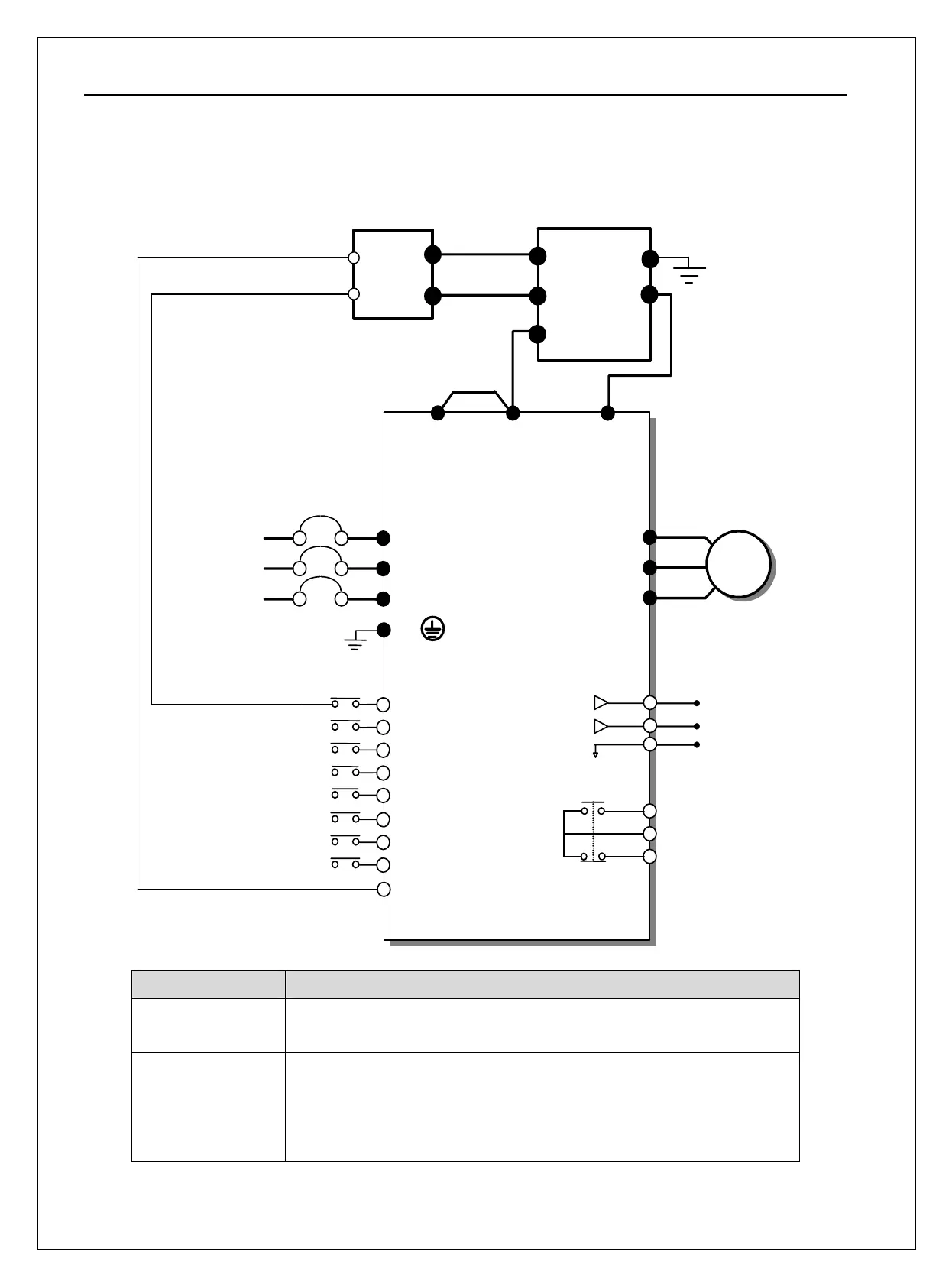
3) Wiring for DB unit and DB resistor (for 5.5~90kW/7.5~125HP inverters)
AC Input
50/60 Hz
U
V
W
G
R(L1)
S(L2)
T(L3)
N(-)
φ
3
MCCB(Option)
M1
M2
M3
M4
M6
M8
M7
MOTO
Programmable Digital Input : Ext Trip
Common Terminal
Fault Contact Output
less than AC250V (DC30V), 1A
P2(+)P1(+)
M5
S1
S0
5G
Output Frequency Meter
Output Voltage Meter
Common for output meter signal
3A
3C
3B
CM
DB Resistor
TH1
TH2
Short
N
B1
G
B2
B2
B1
DB Unit
Max distance between
P & P2: 5m
P
DB resistor terminal Description
B1, B2
Wire the terminal properly based on wiring block diagram.
Connect a DB resistor to the DB Unit’s B1, B2 terminals.
TH1,TH2
Thermal sensor terminal of DB resistor.
Normal temperature (Ambient): Contact ON (TH1-TH2 closed)
DB resistor overheated: Contact OFF (TH1-TH2 Open).
Wire it to the inverter terminal defined as External Trip.

 Loading...


