Chapter 4 - Operation
4-2
Detail description
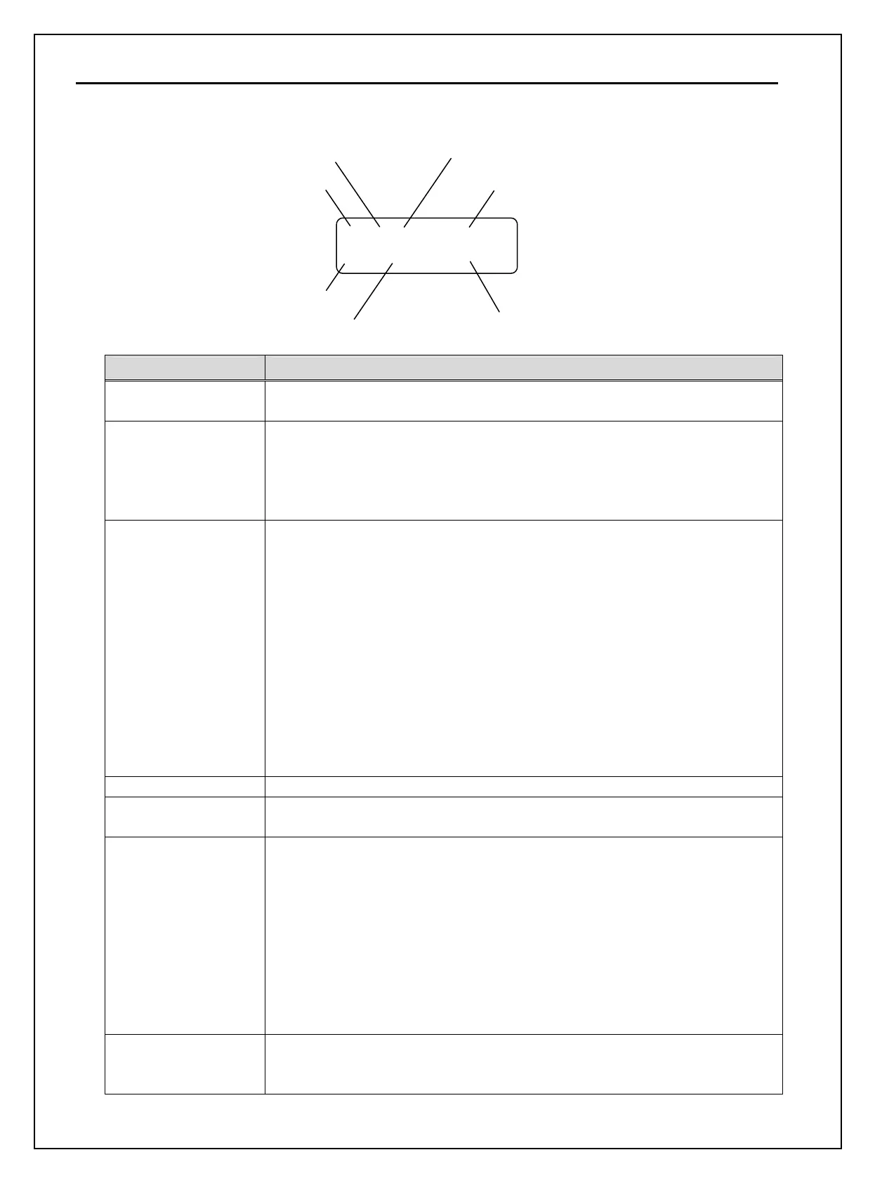
1) LCD Keypad Display
DRV
▶
T/K 0.0 A
00 STP 0.00 Hz
Displays Description
1) Parameter Group Displays the parameter group. There are DRV, FU1, FU2, I/O, EXT, COM, APP
groups.
2) Run/Stop Source Displays the source of motor Run and Stop
K: Run/Stop using FWD, REV buttons on keypad
T: Run/Stop using control terminal input FX, RX
R: Run/Stop using RS485
O: Run/Stop via option board
3) Frequency Setting
Source
Displays the source of command frequency setting
K: Frequency setting using keypad
V: Frequency setting using V1 (0 ~12V or -12~ 12V) or V1 + I terminal
I: Frequency setting using I (4 ~ 20mA) terminal
P: Frequency setting using Pulse input
R: Frequency setting using RS485
U: Up terminal input when Up/Down operation is selected
D: Down terminal input when Up/Down operation is selected
S: Stop status when Up/Down operation is selected
O: Frequency setting via Option board
X: Frequency setting via Sub board
J: Jog terminal input
1 ~ 15: Step frequency operation (except Jog)
4) Output Current Displays the Output Current during operation.
5) Parameter Code Displays the code of a group. Use the ▲(Up), ▼(Down) key to move through
0~99 codes.
6) Operating Status Displays the operation information.
STP: Stop Status
FWD: During Forward operation
REV: During Reverse operation
DCB: During DC Braking
LOP: Loss of Reference from Option Board (DPRAM fault)
LOR: Loss of Reference from Option Board (Communication network fault)
LOV: Loss of Analog Frequency Reference (V1: 0~12V, -10~12V)
LOI: Loss of Analog Frequency Reference (I: 4~20mA)
LOS: Loss of Reference from Sub-Board
7) Inverter Output
Frequency/ Command
Frequency
Displays the Output Frequency during run.
Displays the Command Frequency during stop.
2) Run/Stop Source
3) Frequency Setting Source
4) Output Current
7) Drive Output Frequency During Run,
Command Frequency During Stop
6) Operating Status
5) Parameter Code
1) Parameter group