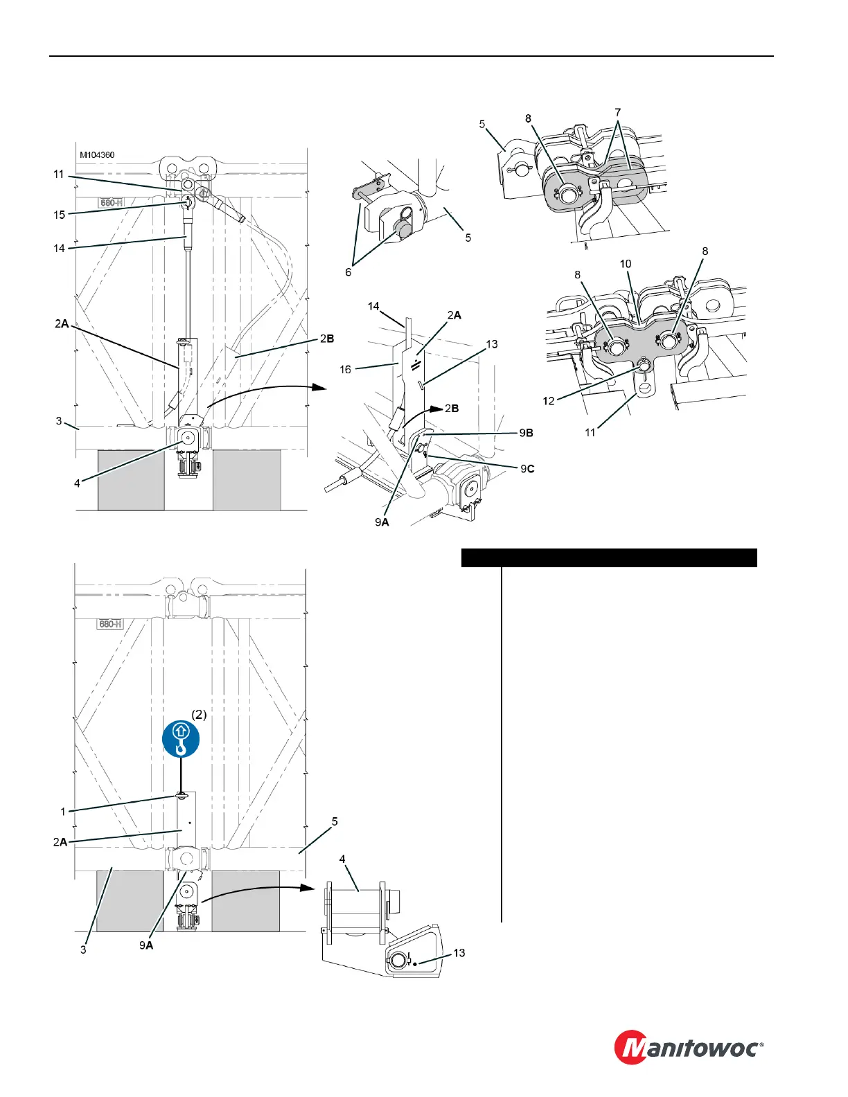
FIGURE 4-77
View A
View B
View D
View C
View E
View F
Item Description
1 Lifting Lug (2)
2Socket (2)
3 Insert (closest to butt)
4 Connecting Pin (2)
5 Adjacent Insert
6 Pin Puller Bracket with Pin (2)
7 Strap Links (4)
8 Pin with Collar, Retaining Pin and Cotter Pins (4)
9 Hitch Pin with Hair-Pin Cotter, 235 mm (2)
10 Links (4)
11 Link (2)
12 Pin with Cotter Pin (2)
13 Hitch Pin with Hair Pin Cotter, 196 mm (2)
14 Drop-Down Suspension Pendant (2)
15 Pin with Cotter Pin (2)
16 Button (10 each pendant)
A Shipping Position
B Pendant Installation Position
C Working Position