Manitowoc Published 08-12-19, Control # 224-13_v2 4-101
MLC650 OPERATOR MANUAL SET-UP AND INSTALLATION
Install Drop-Down Suspension
If the drop-down suspension is required per the Boom
Rigging Drawing in use, install it as follows:
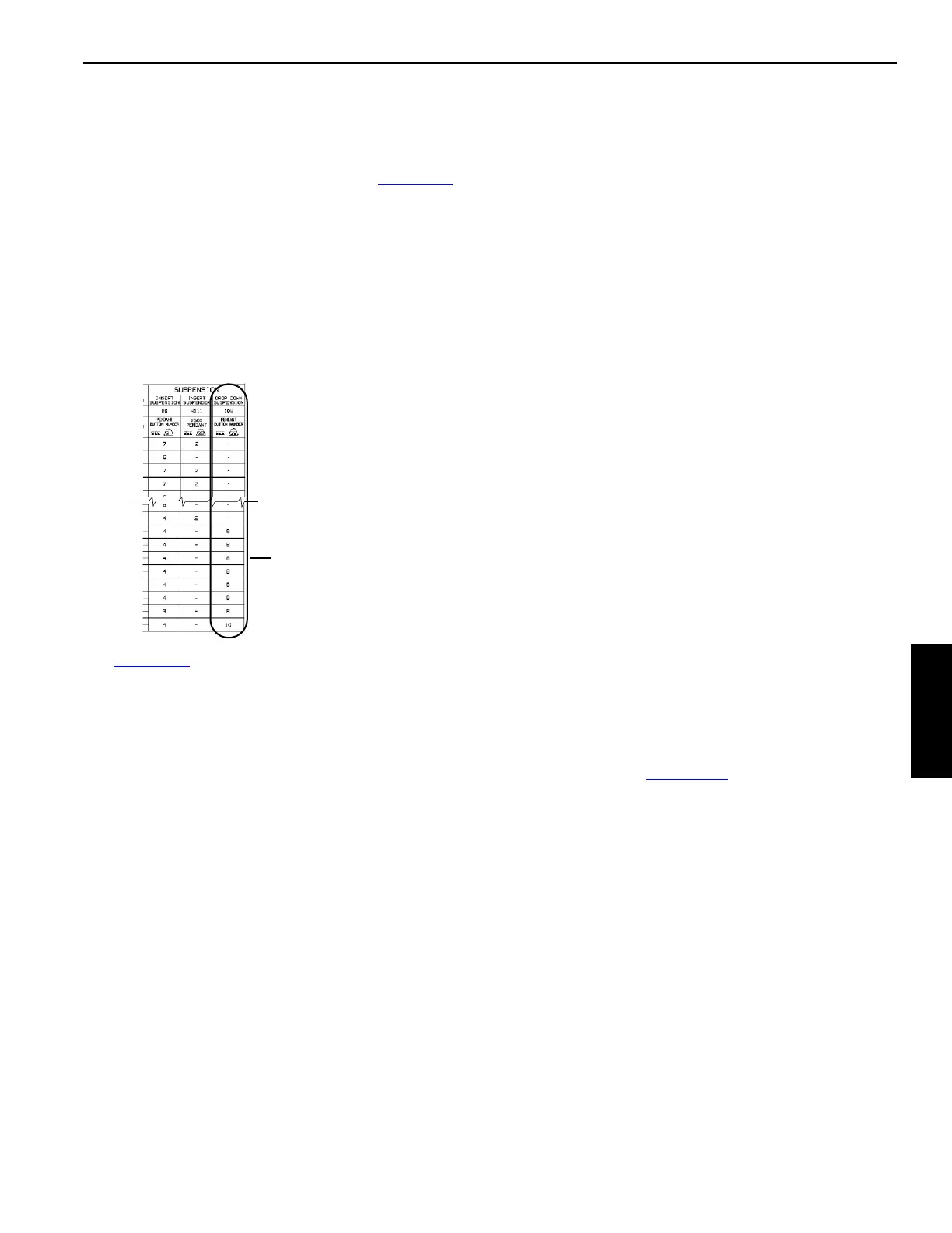
1. Refer to Boom Make-Up Table (see A, Figure 4-78
) in
the appropriate Boom Rigging Drawing at the end of this
section to determine the following:
- Whether or not the drop-down suspension is
required and its location
- Pendant button number that must be pinned to the
sockets
The Boom Make-Up Table will vary from one Boom
Rigging Drawing to another.
See Figure 4-77
for the remaining steps.
2. Make sure the drop-down suspension assembly is in the
shipping position:
• The sockets (2, View A) pinned in the shipping
position (A) (vertical) with the hitch pins (9)
• The hitch pins (13, View A) installed in the drop-
down suspension beam
3. Attach lifting slings from the assist crane to the lifting
lugs (1, View A) on the button sockets (2).
The drop-down suspension assembly weighs 1 000 kg
(2,205 lb).
4. Lift the drop-down suspension assembly into position at
the end of the proper insert (3, View A) so the
connecting pins (4) are in line with the bottom
connectors on the insert.
5. Disconnect the lifting slings.
6. Prepare the adjacent insert (5) as follows:
a. Remove both pin puller brackets and pins (6, View
C) and store them in the parts box.
b. Remove the strap links (7, View D) from both sides
of the insert and store them in the parts box. Place
the pins with collars (8) to the side for use later.
7. Attach the adjacent insert (5, View A) to the insert (3).
8. Block the adjacent insert (5, View A) so the bottom
connecting pin holes are aligned.
9. Remove the bottom connecting pins (4, View A).
10. Reattach lifting slings from the assist crane to the lifting
lugs (1, View A) on the button sockets (2) and lift the
drop-down suspension assembly into position so all of
the connecting holes are aligned (View B).
11. Install the connecting pins (4, View B) so the pin heads
face out and install the safety pins.
12. Remove the socket locking hitch pins (9, View F) from
holes (A) and lower the sockets (2, View B) to the
pendant installation position (B).
13. Install the socket locking hitch pins (9, View F) in holes
(B).
14. Disconnect the lifting slings.
15. Install the drop-down suspension links (10, View E) with
the pins (8). The pin heads must face out.
16. Attach the links (11, View E) to the links (10) with the
pins (12). The pin heads must face out.
17. Lay the drop-down suspension pendants (14, View B)
inside the insert (3) so the open socket ends are toward
the boom top.
18. Pin the drop-down suspension pendants (14, View B) to
the links (11) with the pendant pins (15).
19. Perform the remaining steps as the boom is raised:
a. As the boom straps rise during the boom raising
procedure (page 4-136
), guide the drop-down
pendants through the opening between the boom
inserts. Take care not to damage lacings.
b. Signal the crane operator to stop the boom raising
procedure when the required pendant buttons (16)
are near the sockets (2, View B).
c. Remove the socket locking hitch pins (13, View A)
from the drop-down suspension beam.
d. Position the required pendant button into each
socket (2, View F) and install the button retaining
hitch pin (13).
e. Remove the socket locking hitch pins (9, View F)
from the pendant installation position (B) and store
the pins in the working position (C) to allow the
sockets to pivot as the boom straps rise.
f. Continue with the boom raising procedure.
FIGURE 4-78
Example of Boom Make-Up
Table in Boom Rigging
Drawing
A