7 Additional settings
Adjust the speed controller so that only a small overshoot of the actual speed value
occurs. The overshoot should be approx. 15% higher than the speed setpoint. This setting
applies to most motors that can be operated with the servo drive. If an even "harder"
control response is required, the gain of the speed controller can be increased even
further. In this case, we recommend using a setpoint ramp for the speed control (the limits
of this method are reached when the drive starts to oscillate or to emit noise). The
monitored I²t value may increase as well, indicating that the motor is reaching its
maximum current limit. The control quality depends on the load conditions so that it may
be necessary to readjust it under different load conditions.
Open the menu Options/Input limits and select the maximum possible value for Speed
values/Maximum acceleration to set.
Start the Oscilloscope:
Display/Oscilloscope
Set the following values:
Channel Scaling Offset
Channel 1: Actual speed value 1,000 rpm/div, 1 div
Channel 2: Speed setpoint 1,000 rpm/div, 1 div
Channel 3: Following error 0.2rpm/div, –1 div
Channel 4: Real current - actual value 5A/div, –2 div
Time base: 100ms/div, delay 100ms
Trigger: Source = speed setpoint; Level = 10 rpm;
Mode = normal, rising trigger edge
The reversing generator must be parameterised as follows:
l Reversing distance: 10 rev
l Speed: 1,000 rpm
l Acceleration: (10,000 rpm at first)
l Deceleration: (10,000 rpm at first)
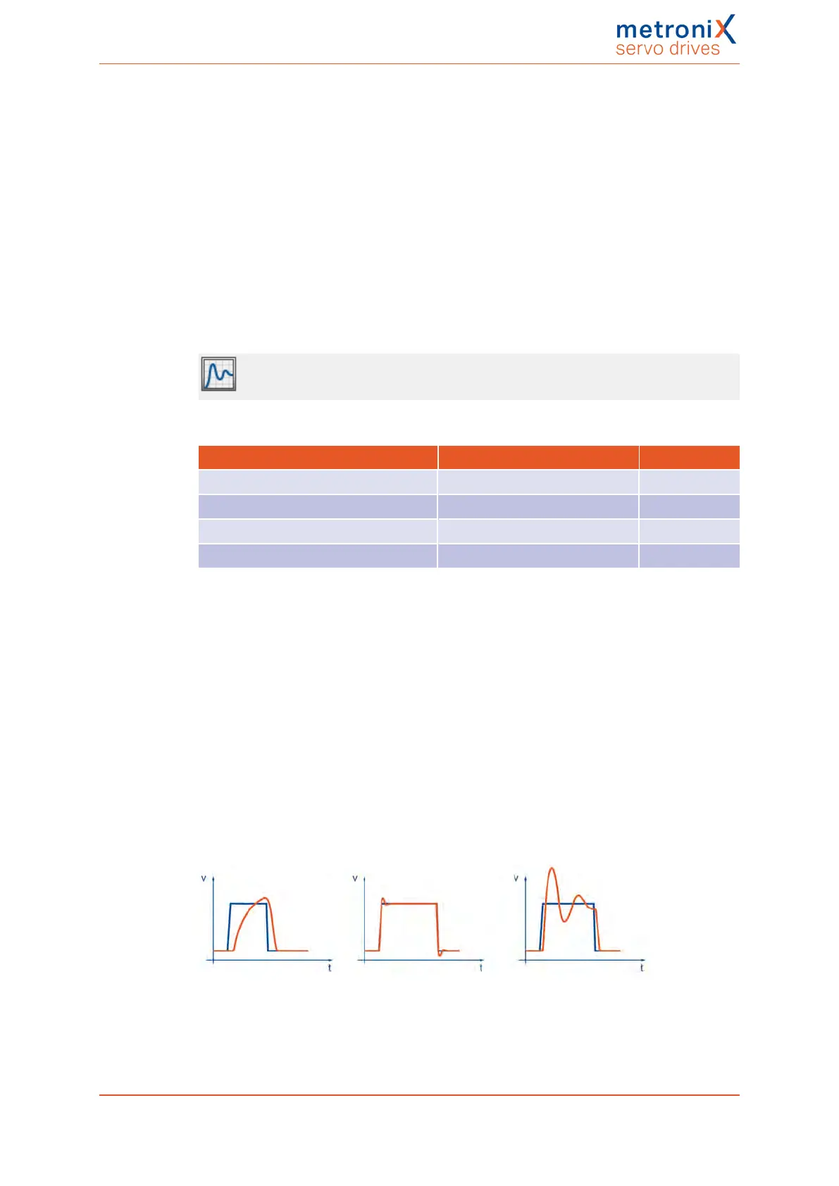
Enable the servo drive. Start the reversing generator. The motor will then reverse within
the specified limits. Check the behaviour when the speed setpoint is reached. It must
correspond to the well-dampened curve (middle curve in the following illustration).
Figure 96: Speed controller: Step responses
Product manual BL 4000-C Page 165 of 298
 Loading...

