2-4
1. Brake
2. Pipeline pressure gauge (s)
Displays the pipeline pressure or the cylinder pressure after relief.
3. Total flowmeter
The medium level of flowtube float indicates the current flow of the mixed gas.
4 Flow control (s)
When the system switch is set to the ON position:
Turn the control counterclockwise to increase the gas flow.
Turn the control clockwise to decrease the gas flow.
5 Electronic flowmeter
Displays the current flow of the corresponding gas.
6. Ventilator control panel
7. Control knob
8. Display
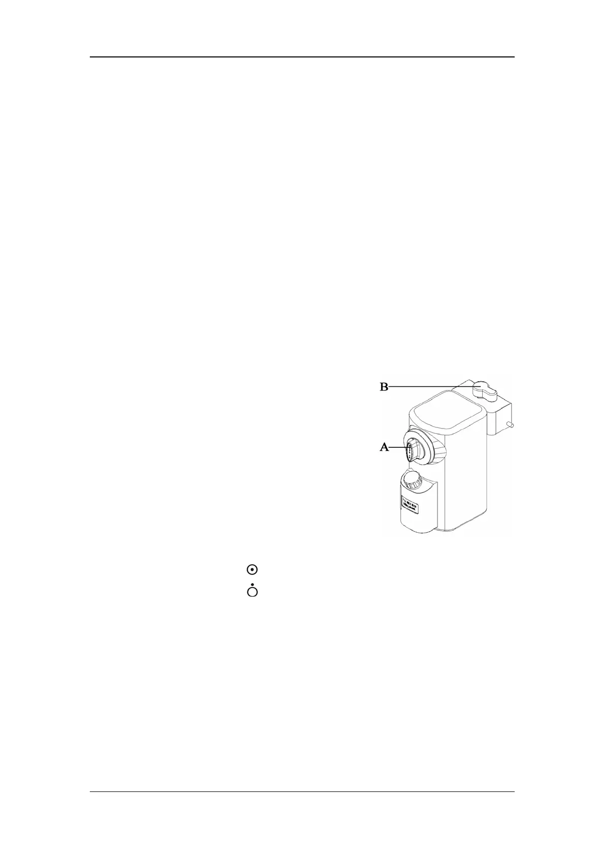
9. Vaporizer
A. Concentration control
Push and turn the concentration control to set the
concentration of anesthetic agent.
B. Locking lever
Turn the locking lever clockwise to lock the vaporizer
in position.
10. Gas supply connector (s)
O
2 ,
N
2
O and AIR connectors are provided.
11. System switch
Set the switch to the position to enable gas flow and to turn on the system.
Set the switch to the position to disable gas flow and to turn off the system.
12. Cylinder pressure gauge (s)
High-pressure pressure gauge (s) that displays cylinder pressure before relief.
13. O
2
flush button
Push to supply high flows of O
2
to the breathing system.
14. Auxiliary electrical outlet
Three auxiliary electrical outlets are provided when the anesthesia machine is
configured with an isolation transformer.
15 Drawer lock
16. Worktable (with drawer)

 Loading...