2 Installation and Wiring
22
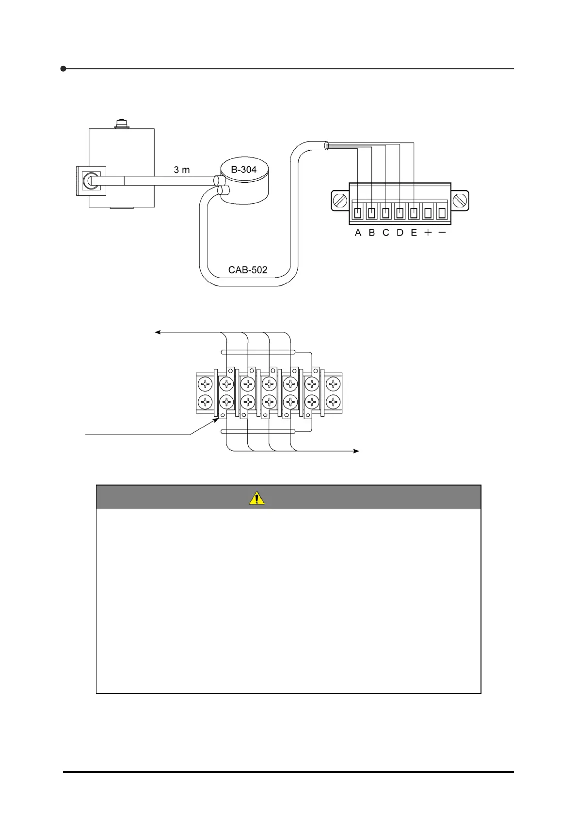
Similar to the connection with one load cell, one load cell and one junction box (B-304) are
connected to the equipment as shown below.
This time, connect signal cables as shown below in the extended junction box.
CAUTION
The signal cable colors shown above are our standard color codes. Each
transducer manufacturer employs unique signal colors for strain-gage-based
transducers such as the load cell. For this reason, check the instruction manual and
inspection result record of the strain-gage-based transducer to be used before
connecting signal cables to the CSD-709.
When you intend to use a tension type or compression and tension type load cell
and define the direction of tension as a positive direction, swap the signal cables of
+SIG and -SIG before connection.
Arrange the CAB-502 cable between junction box and CSD-709 so that the length
of the cable will not exceed 30 m. If the length exceeds 30 m, the input voltage to
the CSD-709 will drop due to cable resistance, creating a risk of deviations from
warranted measurement accuracy.
Terminal pitch: 9.5 mm
To CSD-709
Conforming crimp terminal:
1.25-4 or 2-4
Red Blue White
Green
Red Blue White
Green
Yellow (shield)
Yellow (shield)
Junction box
To load cell