2 Installation and Wiring
23
With respect to the excitation voltage to the strain-gage-based, you can select a voltage level from
2.5 VDC, 5 VDC, and 10 VDC. The selected excitation voltage determines the number of parallelly
connectable strain-gage-based transducers as shown below.
Excitation voltage Number of parallelly connectable transducers
2.5 VDC 8
5 VDC 4
10 VDC 2
For excitation voltage setting procedures, see Section 2.3, "Setting the excitation voltage".
Described below are procedures used to plug in signal cables to the strain-gage-based transducer
connector of the CSD-709.
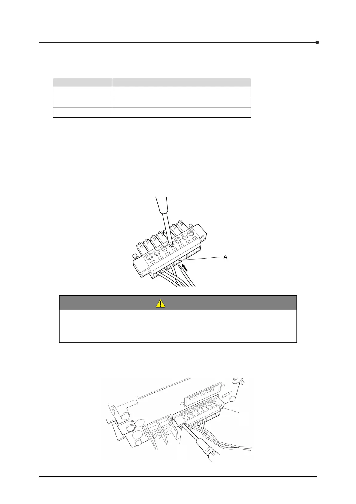
1. Remove the sheath at the end of each signal cable by 6 mm to 7 mm.
2. Insert the signal cable into the hole of the strain-gage-based transducer connector (A) and
tighten the screw at the top face of the connector.
CAUTION
In case of stranded cable, lightly twist core wires so that they will not be separated.
If core wires are twisted excessively, the cable may be easily disengaged from the
connector.
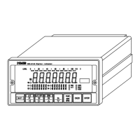
3. Mount the strain-gage-based transducer connector to the CSD-709 and tighten the two screws
(A) at the ends of the connector.